Optical coherence tomography apparatus using optical-waveguide structure which reduces pulse width of low-coherence light

a technology of optical waveguide structure and optical coherence tomography, which is applied in the field of optical coherence tomography apparatus, can solve the problems of inability to distinguish the respective layers based on the reflected light, inability to increase the output power of the sld, and interferen

Inactive Publication Date: 2003-09-09
KK TOPCON +1
View PDF9 Cites 55 Cited by
  • Summary
  • Abstract
  • Description
  • Claims
  • Application Information

AI Technical Summary

Benefits of technology

Generally, the reciprocal of the pulse width of the pulsed laser light emitted from a pulse laser is approximately proportional to the spectral width of the pulsed laser light. That is, when the pulse width is reduced, the spectral width increases, and therefore the coherence length is reduced. Therefore, when the pulse width of the low-coherence light emitted from the light source is reduced, the resolution of the tomographic image can be increased corresponding to the reduction in the coherence length.
(xvii) In the optical coherence tomography apparatus having the feature (xiv), the optical fiber amplifier may comprise a dye-doped optical fiber. In this case, the optical fiber amplifier can achieve a great gain in a desired wavelength band which reflection light belongs to.

Problems solved by technology

However, in practice, the interference between the reference light and the signal light occurs when the difference between the lengths of the optical paths of the reference light and the signal light is equal to or less than the coherence length of the light source, the interference occurs.
Therefore, when the object includes a plurality of layers within a thickness equal to the coherence length, it is not possible to distinguish the respective layers based on the reflected light.
However, it is impossible to increase the output power of the SLD.
In addition, it is also impossible to reduce the pulse width and the coherence length of the SLD since the pulse width of the SLD is determined by its bandgap.
However, in the above apparatus, the light source including the KLM (Kerr-lens mode-locked) Ti:sapphire laser is bulky, expensive, and uneasy to handle.
That is, in practice, the above apparatus using the KLM (Kerr-lens mode-locked) Ti:sapphire laser is not practicable due to its large size, high cost, and poor usability.
In other words, a bulky, expensive, uneasy-to-handle light source, which is required in the conventional optical coherence tomography apparatus, is unnecessary.

Method used


Image

  • Optical coherence tomography apparatus using optical-waveguide structure which reduces pulse width of low-coherence light
  • Optical coherence tomography apparatus using optical-waveguide structure which reduces pulse width of low-coherence light
  • Optical coherence tomography apparatus using optical-waveguide structure which reduces pulse width of low-coherence light

Examples


first embodiment

Advantages of First Embodiment

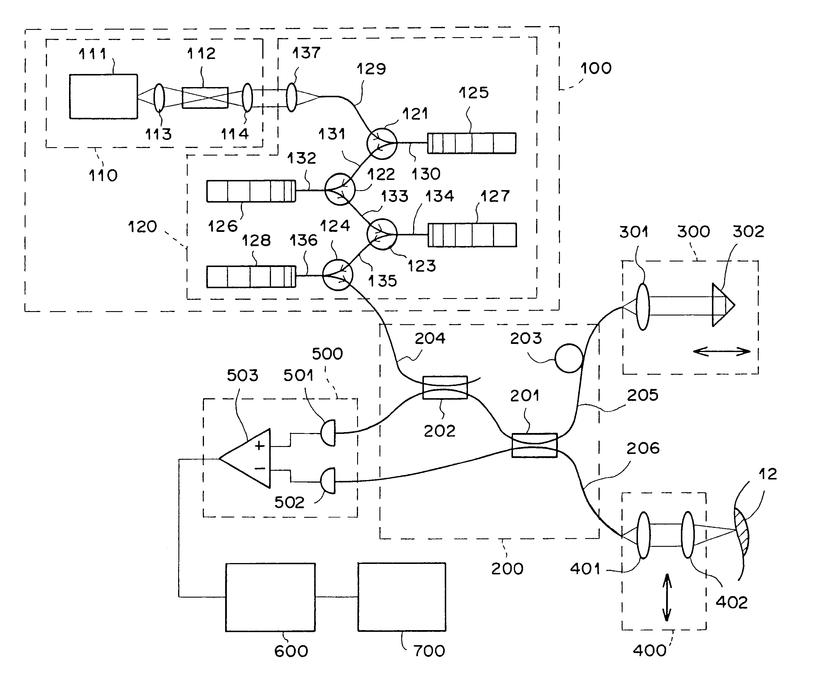
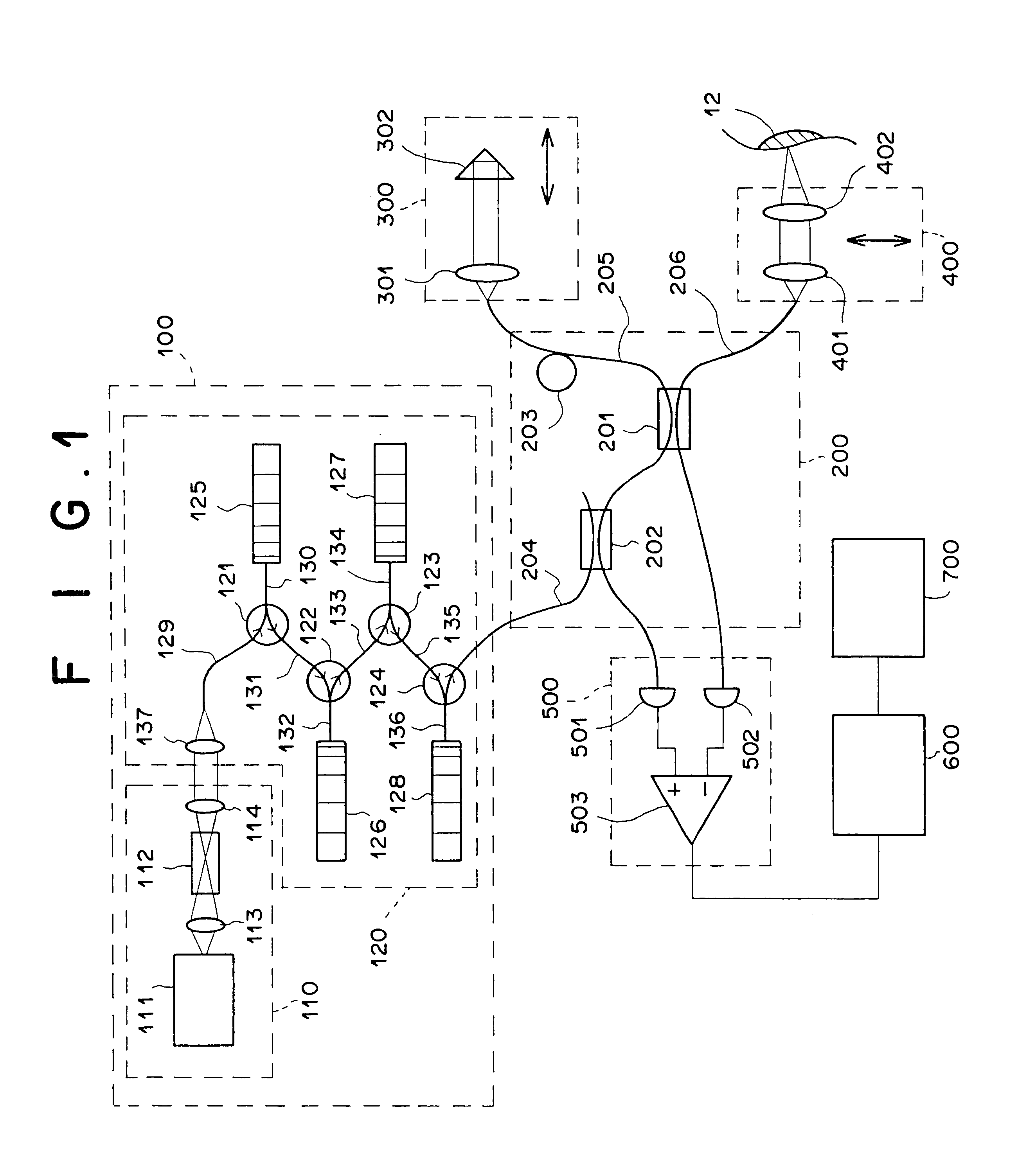
In the first embodiment of the present invention, the light source unit 100 is constituted by the pulsed light source 110 and the pulse-width reduction unit 120, and the pulsed light source 110 is constituted by the erbium-doped fiber laser 111 and the second-harmonic generator 112. In addition, the pulse-width reduction unit 120 reduces the pulse width of the low-coherence light by using the chirped FBGs 125 to 128, which are linear fiber Bragg gratings of the refractive-index modulation type. Therefore, the size and the cost of the light source unit 100 are reduced, and the usability of the light source unit 100 is increased.

In addition, the low-coherence light L1 emitted from the light source unit 100 has a center wavelength of 780 nm, a pulse width of about 5 fs, and a coherence length of 3 micrometers. That is, the resolution in the coherence interference is as high as 3 micrometers. Thus, the resolution in the coherence interference is so increase...

second embodiment

Advantages of Second Embodiment

The optical coherence tomography apparatus as the second embodiment of the present invention has the following advantages as well as the advantages of the first embodiment.

Since the optical fiber amplifier unit 900 is provided, and the reflection light L4 is amplified before the interference with the reference light L2, it is possible to obtain tomographic information having an enhanced signal-to-noise ratio while keeping the intensity of the signal light L3 at such a level that the safety of the portion 12 of the living tissue is secured. In addition, even when the reflection light L4 is returned from a deep area from which the conventional optical coherence tomography apparatuses cannot obtain tomographic information, the interference light L5' generated by the interference between the reference light L2 and the amplified reflection light L4' can be detected, and therefore the tomographic information can be obtained. That is, the depth from which tom...


PUM

PropertyMeasurementUnit
wavelengthaaaaaaaaaa
coherence lengthaaaaaaaaaa

Abstract

In an optical coherence tomography apparatus: low-coherence light from a light source is split into signal light and reference light; at least one of the frequencies of the signal light and the reference light is shifted so as to produce a predetermined frequency difference between the frequencies; the reference light and a portion of the signal light reflected from the object are optically multiplexed so as to produce interference light; and the optical intensity of the interference light is detected in order to obtain a tomographic image of the object. In the light source, the pulse width of pulsed light emitted from a pulsed light source unit is reduced by an optical-waveguide structure. The optical-waveguide structure is made of a material having a normal dispersion characteristic, and includes a structure which realizes an anomalous dispersion characteristic so as to reduce the pulse width of the pulsed light.

Description

1. Field of the InventionThe present invention relates to an optical coherence tomography apparatus which irradiates an object with low-coherence light as signal light, and acquires a tomographic image of the object, where the tomographic image represents information on fine structures on and under a surface of the object, based on the signal light which is reflected from the surface and subsurface portions of the object.2. Description of the Related ArtConventionally, optical coherence tomography apparatuses using low-coherence light are used. In particular, optical coherence tomography apparatuses in which intensities of low-coherence interference light are detected by heterodyne detection are used for obtaining a tomographic image of subretinal fine structures or the like.In the above optical coherence tomography apparatuses, low-coherence light emitted from a light source such as a superluminescent diode (SLD) is split into signal light and reference light, and the frequency of ...

Claims


Application Information

Patent Timeline
Patent Type & Authority Patents(United States)
IPC IPC(8): G01B9/02G01N21/47A61B5/00G02B6/28
CPCG01N21/4795G01B9/02003G01B9/02091G01B9/02014A61B5/0066A61B5/0073G02B6/02085G02B6/2861
Inventor TOIDA, MASAHIRO
Owner KK TOPCON
Why Eureka
Try Eureka