Super-resolution microscope system and method for illumination

a microscope system and super-resolution technology, applied in the field of super-resolution microscope systems and methods for illumination, can solve the problems of excessive intensity of high-intensity lasers against biological cells of specimens, influence on bio-species, etc., and achieve the effects of enhancing resolution, reducing diffractive limits, and enhancing numerical apertures

Inactive Publication Date: 2003-12-23
JAPAN SCI & TECH CORP
View PDF6 Cites 152 Cited by
  • Summary
  • Abstract
  • Description
  • Claims
  • Application Information

AI Technical Summary

Benefits of technology

The microscope of the prior art employs an objective lens having a large numerical aperture so as to enhance the resolution by reducing the diffractive limit, thus its focal depth is extremely reduced, making the focusing operation difficult. In the microscope system of this invention, however, the Bessel beam as the condensing beam of the erase light is a quasi-nondiffractive beam so that its focal depth is substantially enlarged, lightening the focusing burden. In the microscope body, moreover, the resolution is dominated by the erase light so that the operability is enhanced without lowering the resolution.
It is made possible by a condensing optical system using the existing optical element to easily form the condensed beam of the erase light, as exemplified by the Bessel beam having the aforementioned optical characteristics, that is, the condensed beam, having a boundary condition axially symmetric with respect to the optical axis and also having a phase distribution in which a phase is shifted by .pi. at the position symmetric with respect to the optical axis.

Problems solved by technology

Although the erase light has a slightly lower intensity than a high-intensity laser beam of several TW / cm2 in the laser scanning type fluorescence microscope using an unresonance two-photon absorption process, it still has a considerably strong intensity, so that it has raised a problem of influences on the bio-specimen.
This high-intensity laser is excessively strong against the biological cells of a specimen.
Especially in case where a measurement for a long time is required, influence by heat reserve or absorption of multiple photons in the sample is very serious.
This is because disturbance in the intensity distribution leads as it is to deterioration in the resolution of the microscope.
As a result, the beam shape condensed on the specimen surface is not the expected hollow beam, but a deformed beam pattern, thereby causing deterioration in the resolution or reduction in the image quality of a microscope image.
If this zonal aperture is utilized, however, it is difficult to make an optical alignment or to adjust the focal point.
It thus takes a seriously long time to obtain a satisfactory image and needs a skillful technique.
However, in the dye laser there are problems such as a reduction in the quantity of light due to a deterioration in the dye and a frequent, troublesome dye exchange.
The OPO is convenient but remarkably expensive.
Moreover, the OPO is an extremely precise optical system requiring strict managements of humidity and temperature, and a nonlinear optical crystal used has a short lifetime and a high price, thereby making it a light source requiring a serious burden of maintenance and management on the user.
However, for these laser beam irradiations in the various directions, many laser light sources and complex mirror optical systems are required, thereby making the move operation extremely difficult although the capture in one space is possible.
Nevertheless, the specimen is continuously exposed to the laser beam of a high intensity so that it is seriously damaged.
This raises problems that biological cells are photosensitively killed and that a chemical change occurs due to a dissociation or photo-chemical reaction of the molecule themselves.

Method used


Image

  • Super-resolution microscope system and method for illumination
  • Super-resolution microscope system and method for illumination
  • Super-resolution microscope system and method for illumination

Examples


example 1

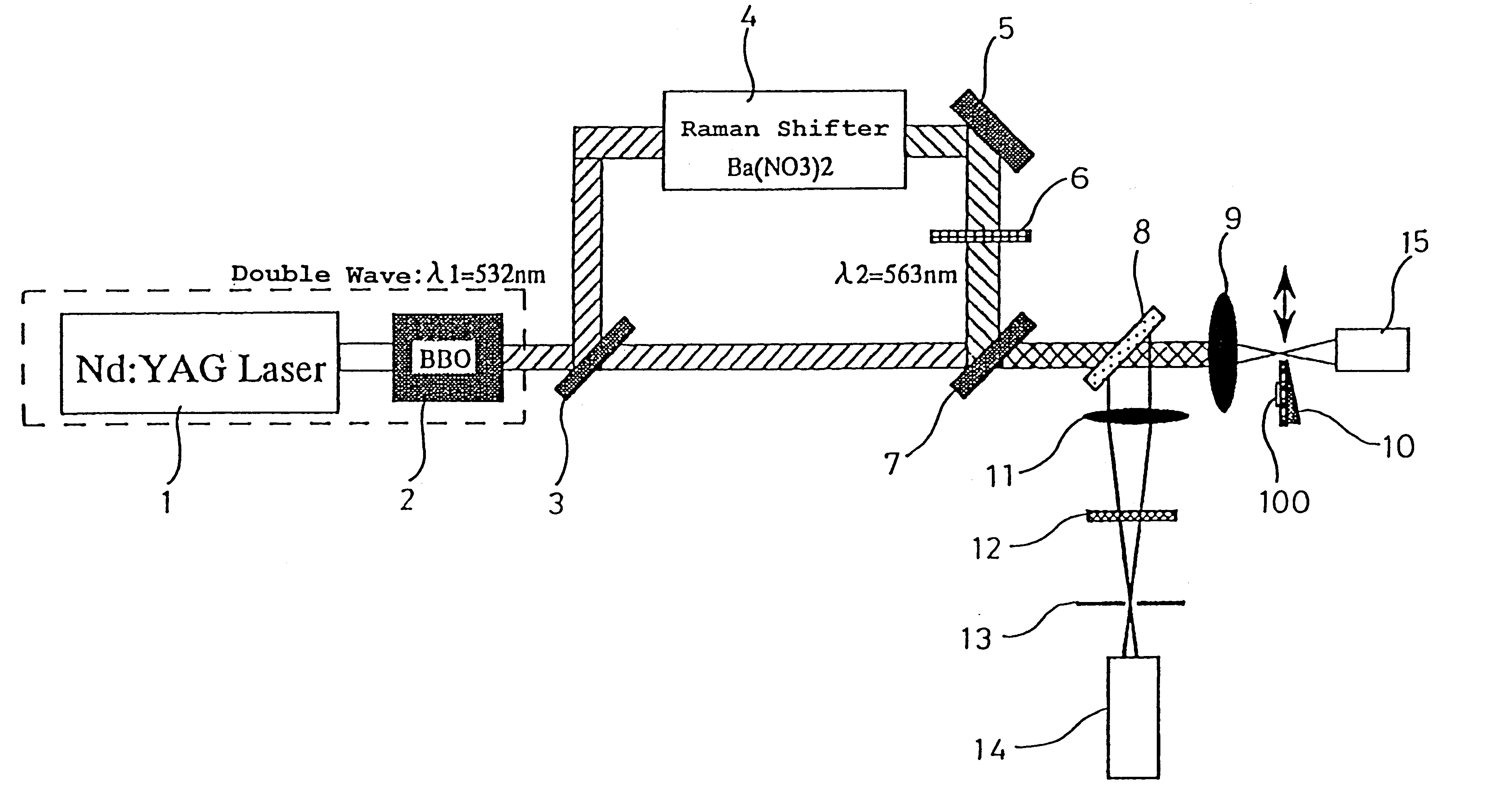
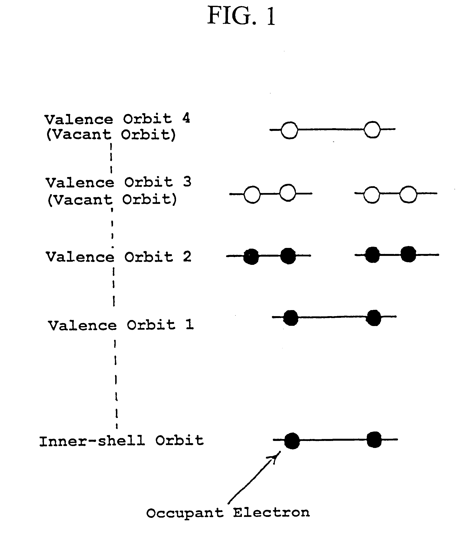
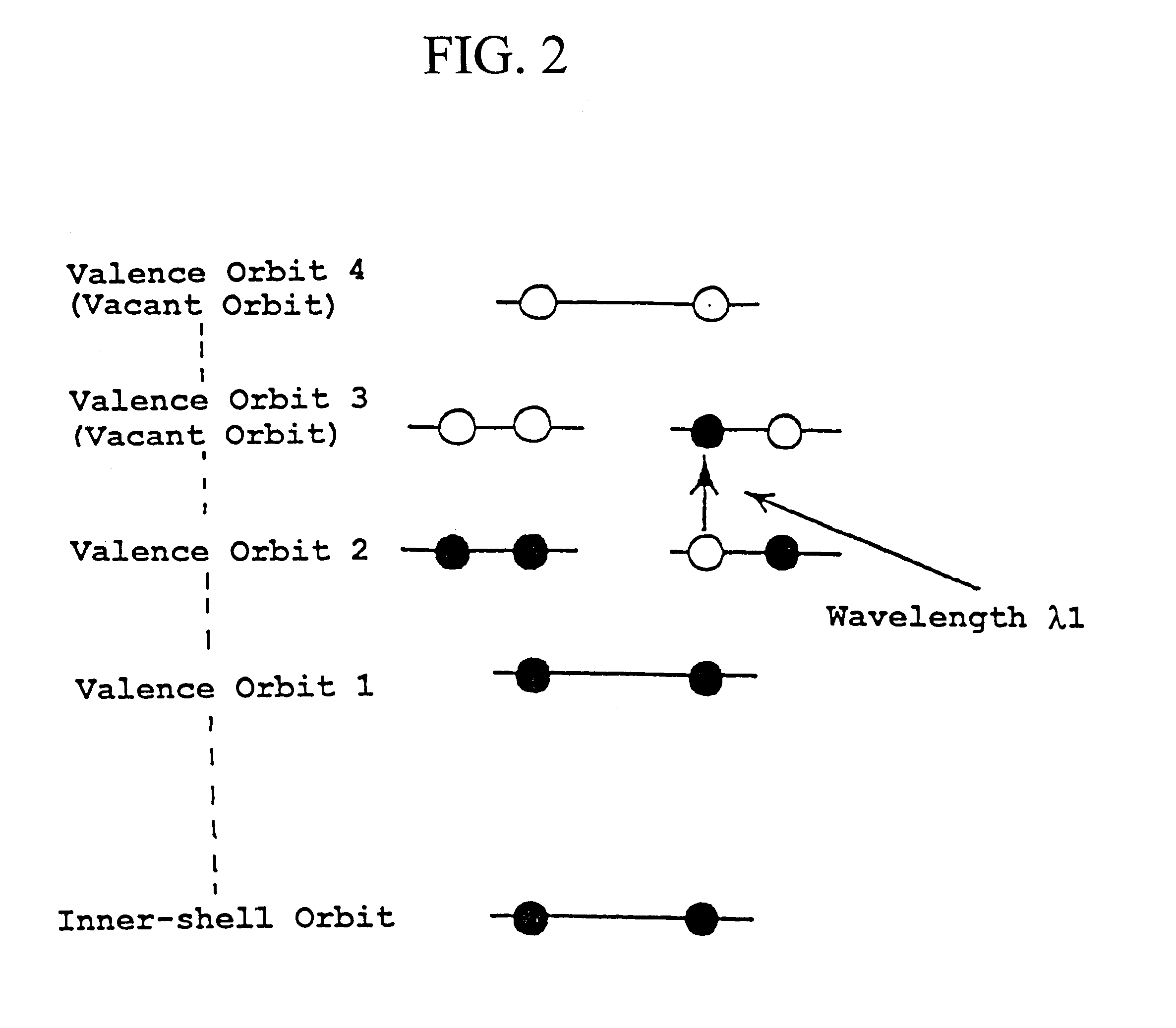
In the microscope system of this invention, the adjusted specimen is dyed with the Rhodamine 6G, and the microscope body is provided with the YAG laser as the light source for the pump light (i.e., the light of the wavelength .lambda.1 for exciting the Rhodamine 6G from the ground state S0 to the first excited state S1).and the light source for the erase light (i.e., the light of the wavelength .lambda.2 for exciting the Rhodamine 6G in the first excited state S1 to the second excited state S2). The microscope body is further provided with the Raman shifter as the wavelength modulating element of the YAG laser.

The Rhodamine 6G can realize, as described hereinbefore, an excellent fluorescent inhibition by double resonance absorption and induced emission, as described hereinbefore, and its excitation wavelength .lambda.1 from S0 to S1 is 532 nm and its excitation wavelength .lambda.2 from S1 to S2 is 560 nm. Hence, the 2-nd harmonics light (=532 nm) of the YAG laser is employed as the...

example 2

In the foregoing Example 1 the condensed beam of the erase light has the phase distribution in which the phase changes continuously from 0 to 2.sigma. when turned once around the optical axis. On the contrary, in the present Example 2, the condensed beam of the erase light has a discontinuously changing phase distribution.

In order to give the discontinuously changing phase distribution to the condensed beam of the erase light, for example, there may be used a phase plate which has a refractive-index distribution (n1.about.n8).changing discontinuously around the optical axis, as illustrated in FIG. 21.

Here, the intensity distribution of the condensed beam of the erase light and the intensity distribution of the fluorescence to be emitted are determined in the case where the fluorescence labeler molecule is the Rhodamine 6G and have the optical parameters and the environmental parameters as shown in the Table 1 and the Table 2, respectively, and the condensing optical system of the mi...

example 3

For the microscope system of this invention, it is the most desirable that the beam obtained by condensing the erase light that is the light of the wavelength .lambda.2 be the 1-st-order-Bessel-beam that is a nondiffractive beam. However, in order to give the microscope body a theoretical super-resolution, the beam may have the aforementioned shape in which the intensity at the central portion is zero.

Therefore, the beam having a phase modulated by the phase plate, as exemplified in FIG. 18 or 22, may be focused in a reduced scale by the ordinary condensing optical system, i.e., the condensing optical system not having the zonal optical system as in the Example 1. Then, although nondiffraction disappears, an excellent super-resolution can be realized.

FIG. 25 illustrates an intensity distribution of a condensed beam of an erase light and a fluorescent intensity distribution, which are calculated when the specimen is dyed with the rhodamine 6G and the shading ratio of the pupil is 0 a...


PUM


Abstract

A microscope system comprising an adjusted specimen and a microscope body, wherein the adjusted specimen is dyed with molecule which has three electronic states including at least a ground state and in which an excited wavelength band from the first electron excited state to the second electron excited state overlaps a fluorescent wavelength band upon deexcitation through a fluorescence process from the first electron excited state to a vibrational level in the ground state. There is provided a novel microscope system which is enabled to condense an erase light for exciting a molecule in the first electron excited state to the second electron excited state in an excellent beam profile by using a simple, compact optical system and which has high stability and operability and an excellent super-resolution.

Description

The invention of this application relates to a microscope system. More particularly, the invention of this application relates to a novel microscope system of high performance and function, which is able to achieve a high quality image of a high spatial resolution by illuminating a dyed specimen with lights of plural wavelengths.In the prior art, there have been developed various types of optical microscopes, and their performance has been enhanced according to the development in the peripheral technique including the laser technique and the electronic graphic technique. As one of these high performance optical microscopes, there has been proposed (in Japanese Patent Application No. 6-329165) a microscope which is able, by using a double resonance absorption process induced by illuminating a specimen with lights of plural wavelengths, not only to control the contrast of an image to be obtained but also to perform a chemical analysis.This optical microscope can, by using the double r...

Claims


Application Information

Patent Timeline
Patent Type & Authority Patents(United States)
IPC IPC(8): G01N21/63G01N21/64G02B21/16G02B21/00G21K7/00G02B21/06
CPCG01N21/636G01N21/64G01N21/6428G01N21/6445G01N21/6458G21K7/00G02B21/0056G02B21/0072G02B21/0076G02B21/16G02B21/0032
Inventor IKETAKI, YOSHINORIFUJII, MASAAKIOMATSU, TAKASHIGE
Owner JAPAN SCI & TECH CORP
Why Eureka
Try Eureka