Thermal regulation of an ion implantation system

a technology of ion implantation and thermal regulation, which is applied in the field of ion implantation systems, can solve the problems of inefficient beam space charge, ion current is restricted by physics limitations, and the transport of standard ions, defined as dopants, such as boron (b.sup.+), arsenic (as, +) and phosphorus (p.sup.+),

Inactive Publication Date: 2003-12-30
ENTEGRIS INC
View PDF13 Cites 19 Cited by
  • Summary
  • Abstract
  • Description
  • Claims
  • Application Information

AI Technical Summary

Benefits of technology

Another object of the present invention is to reduce the time required to service an ion implanter instrument.
A further object of the present invention is to provide shallow implantation depth without the problems normally associated with a low energy beam, such as expanding of the ion beam and the resulting negative effects.
In yet another embodiment, a vapor monitor may be connected to the ion implanter at strategic components along a path of the generated ion beam including, without limitation, at a cool down vaporizer attachment to the ion source housing, an ion source housing, and output vacuum lines, to monitor and verify vapor concentrations of an ion source material and provide another safeguard against possible exposure to a hazardous gas.

Problems solved by technology

As such, these smaller and thinner requirements challenge the ability of present systems to produce high dose ion beams with the low energy required to implant a high concentration of ions at a shallow depth in the semiconductor device
However, low energy ion beams are used for shallow implants, but, for standard dopant atomic ions at low beam energies, ion current is constrained by physics limitations associated with extraction and transport losses
However, as beam energy decreases to accommodate thinner devices, beam transport of standard ions, defined as dopants, such as boron (B.sup.+), arsenic (As.sup.+) and phosphorus (P.sup.+), becomes inefficient due to beam space charge.
However, the use of heavy molecular ions, such as decaborane, creates some unique health and safety challenges.
For example, the vapor pressure of decaborane is low at room temperature (at the threshold limit value), and can be hazardous at modestly elevated temperatures.
Due to the high cost of owning an ion implant system and the need to minimize down time, sources are frequently removed at temperatures significantly above room temperature.
Toxic solids with thermally sensitive vapor pressure, like decaborane, are not routinely used at present, but the removal of a warm walled source with decaborane deposits would present a serious safety risk.
Opening the system before cooling to room temperature may introduce a number of serious health issues dependent upon the ion source materials.
As described hereinabove, the use of decaborane, although not as hazardous as some, still creates some unique health and safety challenges.
Although decaborane is reduced into harmless boron at refractory temperatures, at temperatures ranging between refractory and slightly about room temperature, the possibility of deposits on components of an ion implant system can pose a potential health hazard.
As such, if the ion source chamber is not completely cooled to room temperature, or below, and decaborane deposits are present, an immediate health hazard is encountered.
The implied cost of waiting hours for the ion source to cool to room temperature would be a significant barrier to adoption of decaborane technology in semiconductor manufacturing.
Also, it is obvious that removing a decaborane ion source at elevated temperatures would create an immediate inhalation hazard to personnel.
Also, evaporated decaborane could contaminate the surrounding work area.

Method used


Image

  • Thermal regulation of an ion implantation system
  • Thermal regulation of an ion implantation system
  • Thermal regulation of an ion implantation system

Examples


Embodiment Construction

The present invention provides for temperature control means in an ion implanter to reduce the chance of accidental exposure to harmful ion source material and to provide a more efficient and cost effective means for cooling the ion implanter before servicing or replacing material in an ion source.

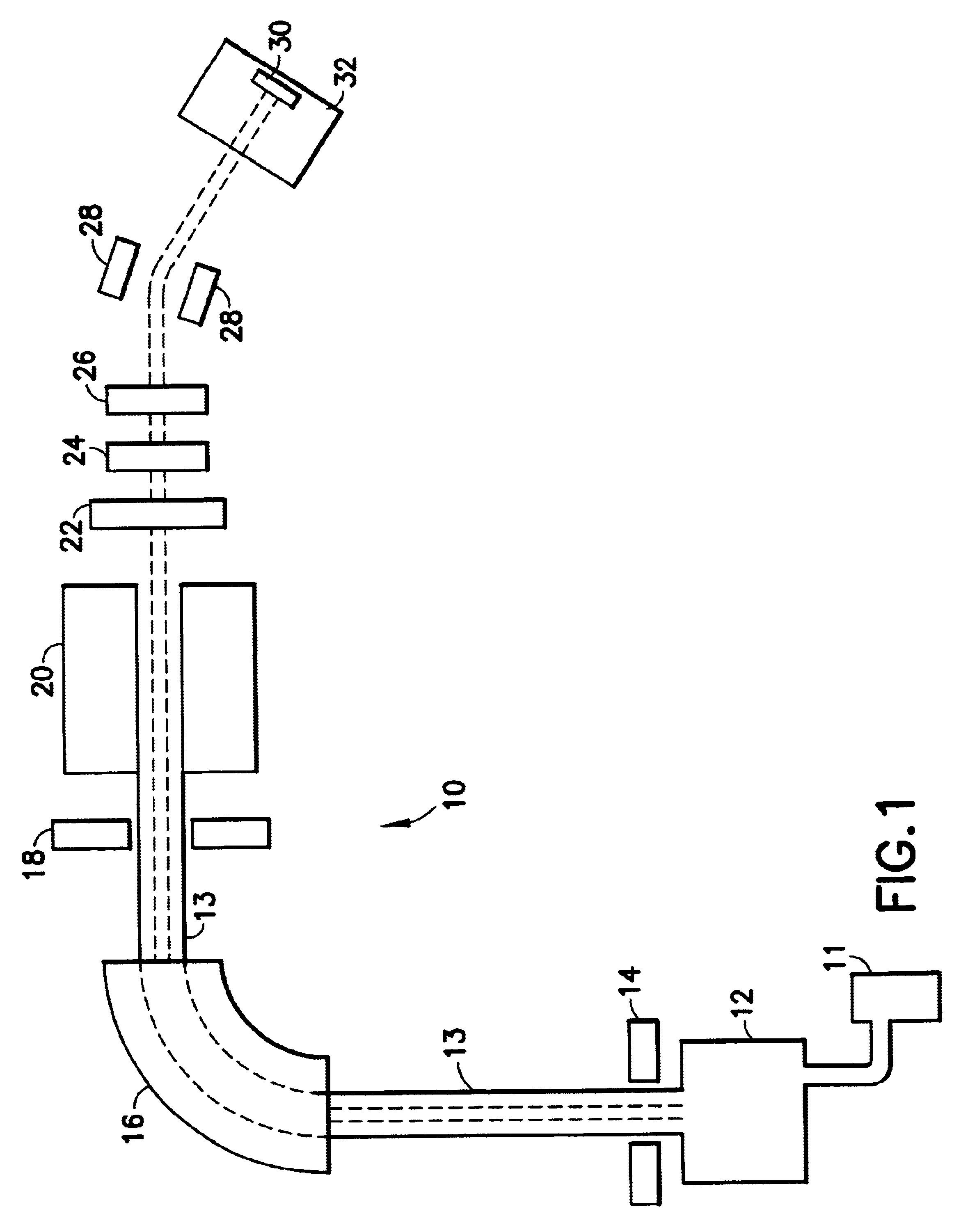
As depicted in FIG. 1, an ion implanter 10 typically includes an ion source 12 that generates ions. The ions are drawn by extracting electrodes 14 and their mass is analyzed by a separating electromagnet 16. The ions are separated by apertures 18 and may be further accelerated or decelerated by accelerators 20 to the final energy. A beam of ions is converged on a sample 30, may also be positioned in a target chamber 32, by quadrupole lens 22 and scanned by scanning electrodes 24 and 26 to uniformly distribute the ion beam on the target 30. Deflection electrodes 28 are designed to deflect the ion beam in order to eliminate uncharged particles caused by collision with residual gas. It should...


PUM


Abstract

A thermoregulation system for an ion implantation system to reduce the temperature in the ion implanter and components therein, or attached thereto, to a temperature at which an ion source material, used in the ion implanter, has a vapor pressure that yields a reduced concentration of vapors. Such arrangement markedly reduces the risk of exposure to harmful vapors from the ion source material.

Description

1. Field of the InventionThe present invention relates to an ion implantation system, and more particularly, to thermal regulation of an ion implantation system to reduce the temperature therein and to minimize the risk of exposure to harmful vapors.2. Description of the Related ArtNumerous semiconductor manufacturing processes employ ion implantation for forming a p-n junction by adding dopants (impurities), such as boron (B) and phosphorus (P) to a semiconductor substrate. Ion implantation makes it possible to accurately control the concentration and depth of impurities to be diffused into a target spot on the semiconductor substrate.Typically, an ion implanter includes an ion source that ionizes an atom or molecule of the material to be implanted. The generated ions are accelerated to form an ion beam that is directed toward a target, such as a silicon chip or wafer, and impacts a desired area or pattern on the target. The entire operation is carried out in a high vacuum.The tren...

Claims


Application Information

Patent Timeline
Patent Type & Authority Patents(United States)
IPC IPC(8): H01J37/08H01J37/317H01J27/02H01J27/04H01J27/08H01L21/265
CPCH01J37/3171H01J37/08
Inventor VELLA, MICHAEL C.
Owner ENTEGRIS INC
Why Eureka
Try Eureka