Solid electrolytic capacitor, and method for preparing the same

a solid electrolytic capacitor and electrolyte layer technology, applied in the direction of capacitor dielectric layers, electrical apparatus casings/cabinets/drawers, coupling device connections, etc., can solve the problems of lowering the electrical conductivity of the electrolyte layer, and affecting the performance of the capacitor

Inactive Publication Date: 2003-12-30
TOKIN CORP
View PDF8 Cites 34 Cited by
  • Summary
  • Abstract
  • Description
  • Claims
  • Application Information

AI Technical Summary

Problems solved by technology

In the step of forming the solid electrolyte layer, the dielectric layer is likely to be damaged.
However, the Ta solid electrolytic capacitor prepared through the above-described steps has problems which affect basic characteristics thereof, i.e., formation of so-called defective portions and lowering of electrical conductivity of the electrolyte layer.
Causes of the formation of defective areas include (A) inclusion of impurities in Ta, (B) irregularity of current in the chemical conversion step and (C) external mechanical stress, and it is believed that any of these causes cannot completely be prevented from occurring in the existing methods for preparing a solid electrolytic capacitor.
Since thicknesses of the dielectric layer in the defective portions are smaller than that in the other area, local intensifications of field strength are likely to occur in such defective portions.
Locally elevated temperatures caused by the local intensifications of field strength rise to crystallizations of the dielectric layer to result in dielectric breakdowns of the dielectric layer.
However, the step of re-treatment for chemical conversion is insufficient as means for repairing the dielectric layer.
A capacitor having high ESR has a drawback that its characteristics in a high frequency range are poor.
However, there is an upper limit with respect to the density of the electrically conductive particles which allows the electrolyte layer to effectively function as a semiconductor layer.
In other words, incorporation of the electrically conductive particles in an excess amount causes deterioration of basic characteristics of the capacitor, in particular, increase of LC.
This is because the electrically conductive particles can be distributed non-uniformly due to thermal expansion, heat contraction or the like caused in the steps of the preparation of the solid electrolytic capacitor, in particular, the step of molding a resin or the step of welding to form areas where the electrically conductive particles are distributed locally at high densities on the surface of the dielectric layer.
Accordingly, studies have not been made from the viewpoint to realize compatibility between low ESR and low LC.
If the size is smaller than about 1 .mu.m, improvement in initial ESR characteristics is likely to be insufficient.
If the size exceeds about 1,000 .mu.m, deterioration of ESR characteristics becomes non-negligible in use for a long period of time.
If the size is smaller than about 1 .mu.m, improvement in initial ESR characteristics is insufficient.
If the size exceeds about 1,000 .mu.m, deterioration of ESR characteristics becomes non-negligible in use for a long period of time.
If the amount exceeds 4,000 parts by weight, viscosity of the solution for forming the electrolyte layer is increased to cause unevenness in application.
If the concentration is lower than about 0.1% by weight, the non-conductive particles are placed in the interface between the dielectric layer and the electrolyte layer in a low density, so that function to prevent local intensifications of field strength is likely to be insufficient.
If the concentration is higher than about 0.5% by weight, the viscosity of the colloidal dispersion becomes high, so that it becomes difficult to place the non-conductive particles in the interface between the dielectric layer and the electrolyte layer.

Method used


Image

  • Solid electrolytic capacitor, and method for preparing the same
  • Solid electrolytic capacitor, and method for preparing the same
  • Solid electrolytic capacitor, and method for preparing the same

Examples


example 1

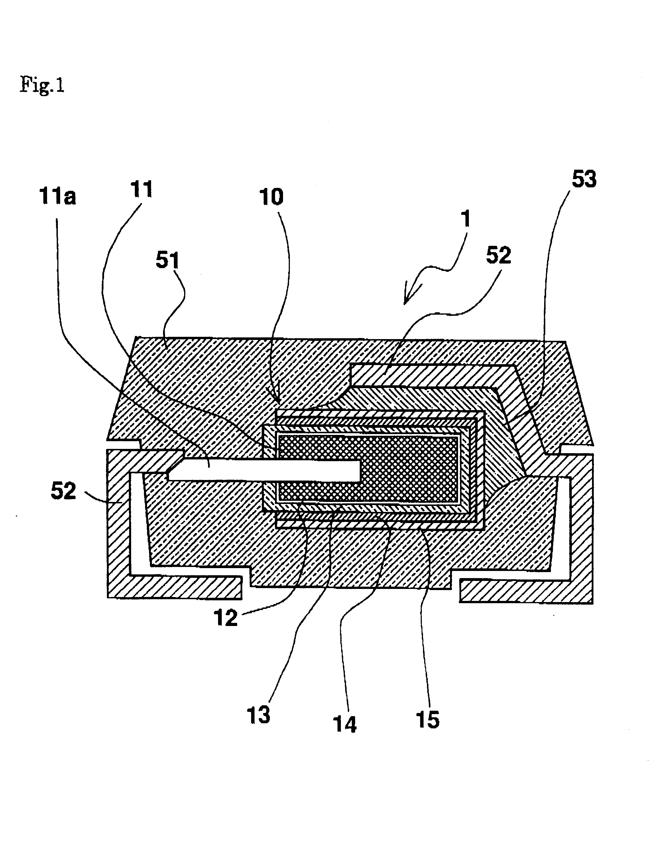
A tantalum powder in which an element lead wire made of tantalum is partially inserted and which has a CV value of 50 kcv / g was charged into a pelleter and pressed, the pressed product was sintered at a temperature of 1,350degreeC. in a vacuum atmosphere of 10.sup.-4 Pa or higher vacuum to obtain a porous anode body having a parallelepipedonal shape.

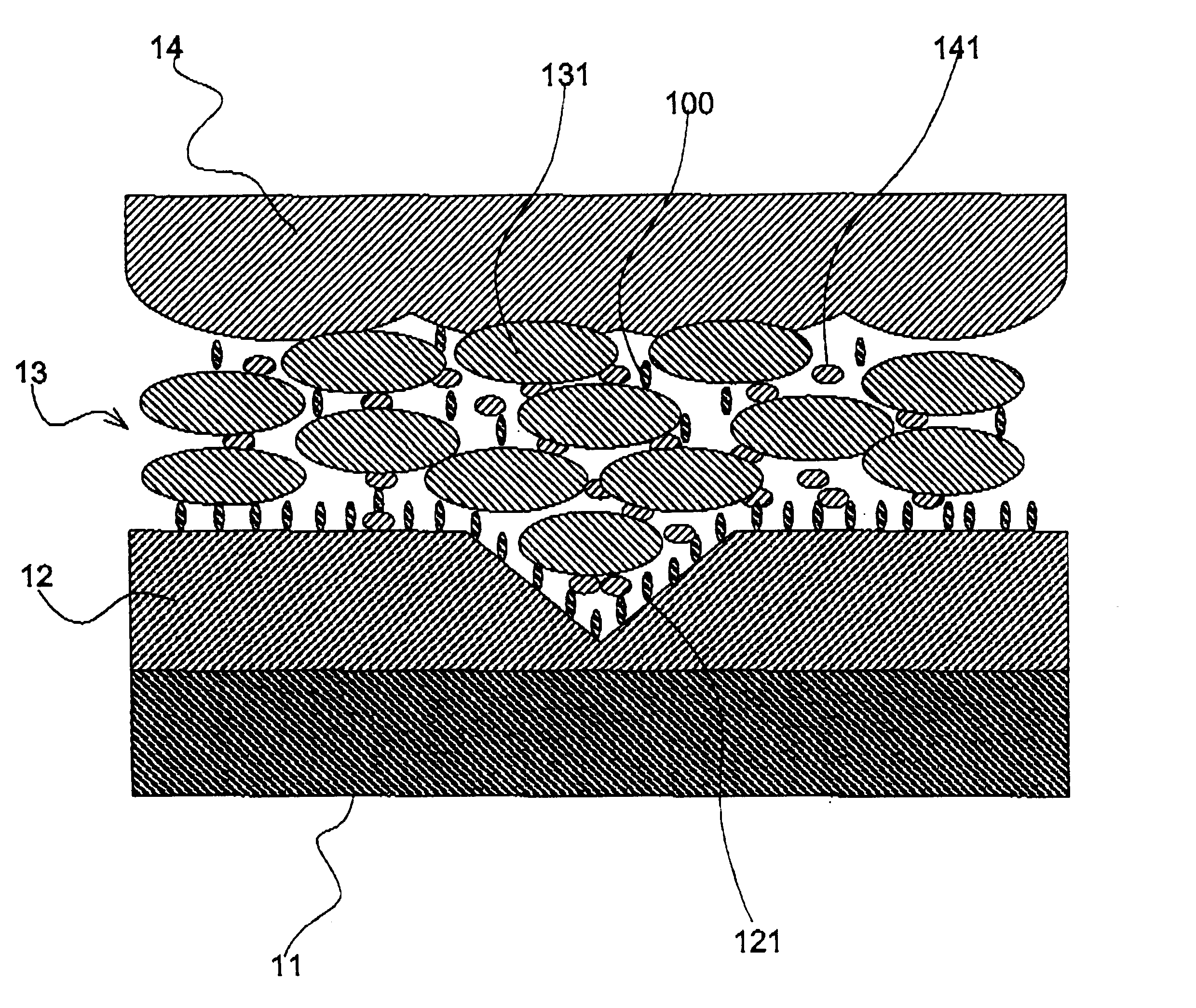
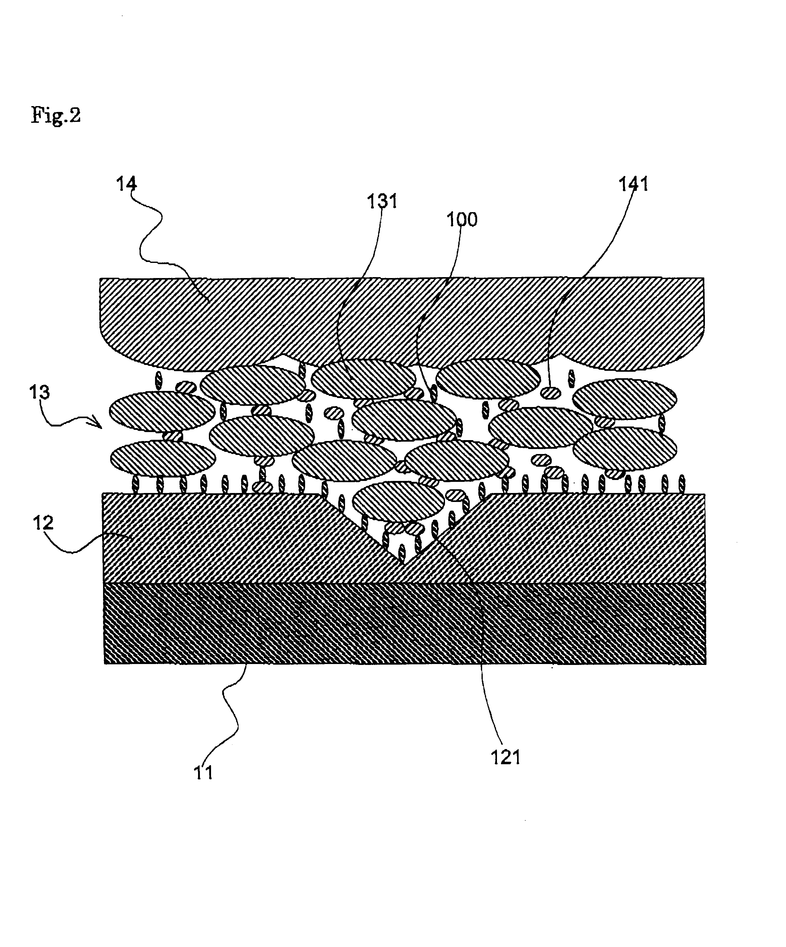
The anode body was soaked in an aqueous solution of 0.6% by volume phosphoric acid and subjected to anodic oxidation with application of a voltage of 33.7 volt for 180 minutes to thereby form a dielectric layer having a large number of pores.

The resulting pellet was soaked in an oxidizing agent solution prepared by dissolving 400 g of ferric benzenesulfonate in 1000 g of an alcohol at room temperature for 5 minutes, and then dried.

Subsequently, the resulting pellet was soaked in an aqueous solution which contained 5% by weight of graphite particles having an average diameter of 1.0.times.10.sup.-5 m and 5 to 7% by volume of pyrrole as a ...


PUM

PropertyMeasurementUnit
sizesaaaaaaaaaa
sizesaaaaaaaaaa
sizeaaaaaaaaaa

Abstract

A solid electrolytic capacitor is disclosed which combines low LC with Low ESR and which has good characteristics even in a high frequency range, and a method for preparing the same is also disclosed. In the solid electrolytic capacitor whose electrolytic layer contains electrically conductive particles, non-conductive particles are present in at least a part of an interface between a dielectric layer and the electrolyte layer. By employing the structure, local intensifications of field strength in the dielectric layer are prevented to enable a problem of increase in LC to be overcome while keeping ESR low. By the method which comprised a step of applying a colloidal dispersion containing the non-conductive particles in the form of colloidal particles to the post-electrolytic layer formation step product, the solid electrolytic capacitor having the above-mentioned structure can be prepared efficiently.

Description

1. Field of the InventionThe present invention relates to a solid electrolytic capacitor and a method for preparing the same.2. Description of the Prior ArtHeretofore, a solid electrolytic capacitor has comprised an anode, a dielectric layer, an electrolyte layer, and a cathode. Generally, a solid electrolytic capacitor has had a structure comprising an anode made of a metal exhibiting valve action (valve metal), an oxidized layer as a dielectric layer formed over the surface of the anode, an electrolyte layer as a semiconductor layer formed on the dielectric layer, and a cathode (made of graphite or the like) formed on the electrolyte layer.In this connection, the valve metal means a metal capable of forming an oxidized layer whose thickness can be controlled by anodic oxidation. Specifically, valve metal includes niobium. (Nb), aluminum (Al), tantalum (Ta), titanium (Ti), hafnium (Hf) and zirconium (Zr). Actually, however, aluminum and tantalum are mainly used.With respect to alum...

Claims


Application Information

Patent Timeline
Patent Type & Authority Patents(United States)
IPC IPC(8): H01G9/02H01G9/00H01G9/07H01G9/025H01G9/028H01G9/032
CPCH01G9/025H01G11/56H01G11/48Y02E60/13H01G9/02
Inventor ARAKI, KENJIFUNAYA, OSAMUARAI, SHINJI
Owner TOKIN CORP
Why Eureka
Try Eureka