

Method and apparatus for electrodeionization of water
a technology of electrodes and water, applied in the direction of water/sewage treatment by ion exchange, non-contaminated water treatment, refrigeration components, etc., can solve the problems of removal of silica and boron, and achieve the effect of preventing the production of chlorine in the electrode compartmen
Inactive Publication Date: 2004-05-11
KURITA WATER INDUSTRIES LTD
View PDF10 Cites 34 Cited by
- Summary
- Abstract
- Description
- Claims
- Application Information
AI Technical Summary
Benefits of technology
The present invention provides an electrodeionization apparatus that can remove silica and boron from water at a high ratio, a method of operating the apparatus, and a system for producing ultra pure water using the apparatus. The apparatus has alternating anion-exchange membranes and cation-exchange membranes arranged between the electrodes, with concentrating and desalting compartments filled with ion-exchanger or activated carbon. The apparatus can decrease the silica or boron concentration in the product water by introducing concentrated water with lower concentration of silica or boron near the outlet for the deionized water. The method of operating the apparatus involves introducing electrode water and concentrated water into the system and controlling the flow of water to remove silica or boron from the system. The system includes a device for introducing electrode water and a device for introducing raw water into the desalting compartments. The invention provides an efficient and effective solution for producing ultra pure water.
Problems solved by technology
The above conventional electrodeionization apparatus do not remove silica and boron at extremely high ratio.
Method used
View moreImage
Smart ImageViewing Examples

Examples
example 2
Deionization was conducted under the same conditions as Example 1 except that the raw water was prepared by adding sodium silicate into ultra pure water to have sodium silicate concentration of 300 ppb (SiO.sub.2 conversion).
The raw water contains low ion concentration, so that it is difficult to ensure required current. However, the product water had high-purity such that silica concentration was 0.1 ppb or less (under the detection limit).
Applied voltage for the above experiment was also 9.7 volts in total, that is, desalting compartment: 1.28V.times.2, concentrating compartment: 1.28V.times.3, anolyte compartment: 1.4V, and catholyte compartment: 1.9V.
Login to View More PUM
| Property | Measurement | Unit |
|---|---|---|
| velocity | aaaaa | aaaaa |
| thickness | aaaaa | aaaaa |
| current efficiency | aaaaa | aaaaa |
Abstract
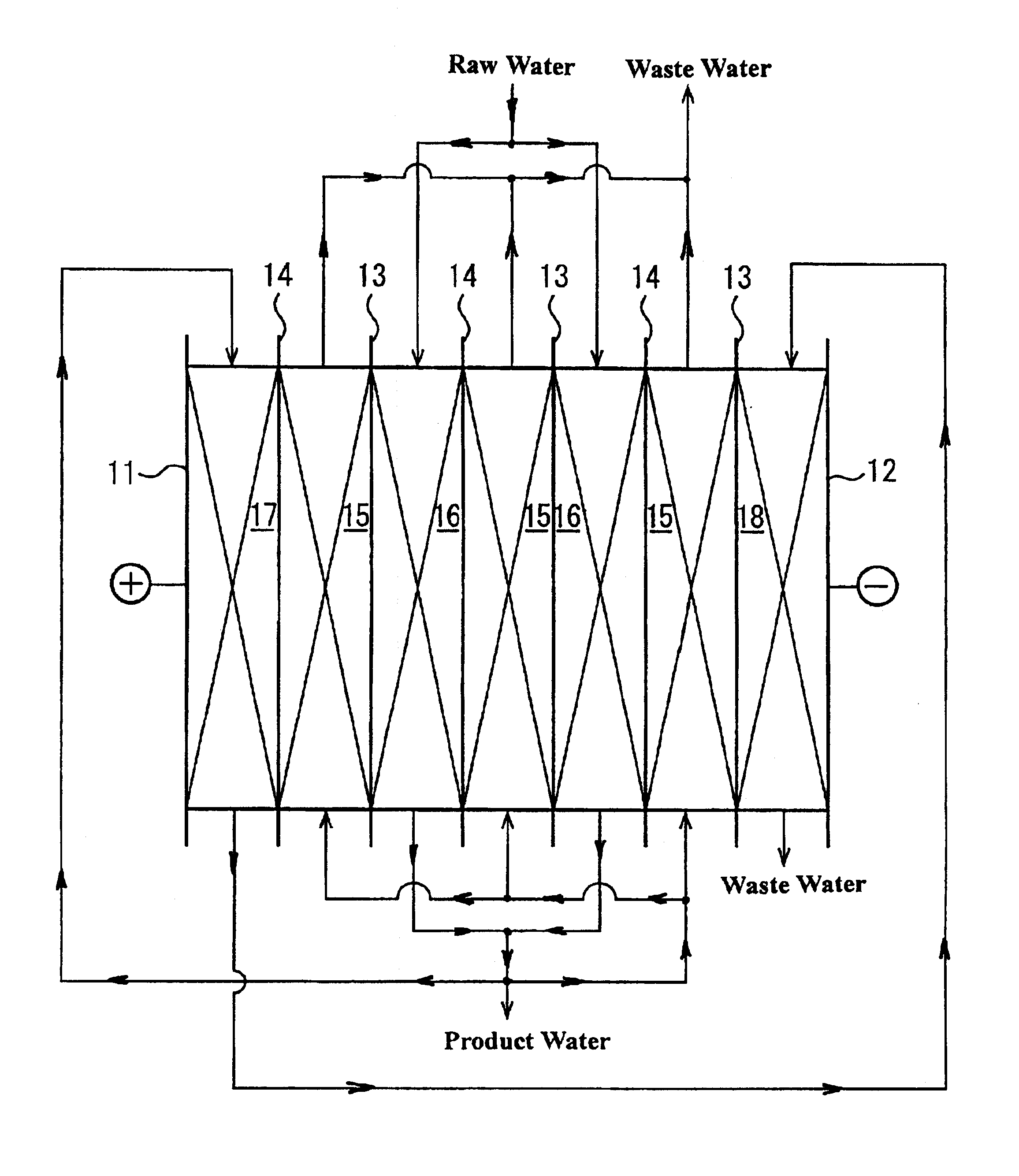
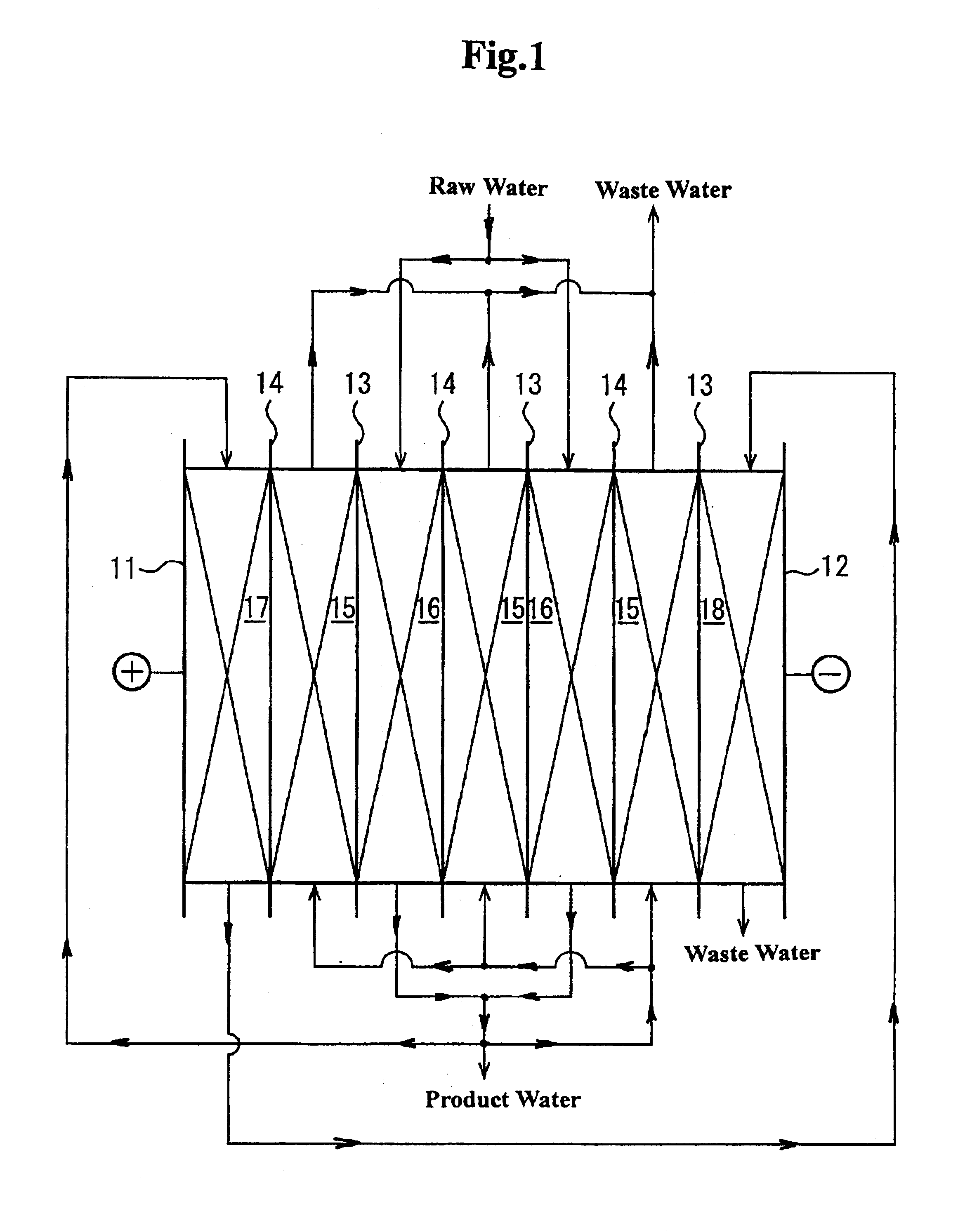
An electrodeionization apparatus has an anolyte compartment 17 having an anode 11, a catholyte compartment 18 having a cathode 12, concentrating compartments 15, and desalting compartments 16. The concentrating compartments 15 and the desalting compartments 16 are alternately formed between the anolyte compartment 17 and the catholyte compartment 18 by alternately arranging a plurality of anion-exchange membranes 13 and a plurality of cation-exchange membranes 14. The desalting compartments 16 are filled with ion-exchanger and the concentrating compartments 15 are filled with ion-exchanger, activated carbon, or electric conductor. Electrode water flows into the anolyte compartment 17 and the catholyte compartment 18. Concentrated water is introduced into the concentrating compartments 15. Raw water is fed into the desalting compartment 16 to produce the deionized water from the desalting compartment 16. Water containing silica or boron at a lower concentration than the raw water is introduced into the concentrating compartments 15 as the concentrated water in a direction from a side near an outlet for the deionized water toward a side near an inlet for the raw water of the desalting compartments 16. At least a part of concentrated water flowing out of the concentrating compartments 15 is discharged out of a circulatory system.
Description
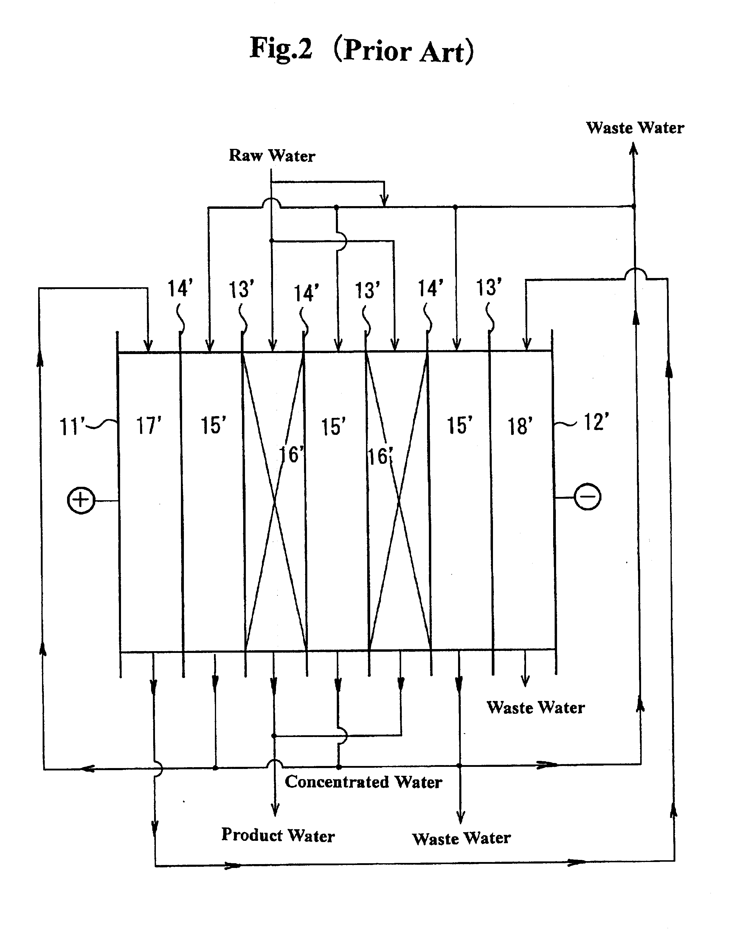
The present invention relates to an electrodeionization apparatus, a method of operating an electrodeionization apparatus, and a system for producing ultra pure water.Deionized water is used for various purposes, for example, in plants such as for semiconductor production and liquid crystal display production, in industrial facilities such as for pharmaceutical industry, food industry, and electric power industry, even in households, and in laboratories. Electrodeionization apparatuses are frequently used to produce deionized water as described in Japanese Patent No. 1782943, Japanese Patent No. 2751090, and Japanese Patent No. 2699256. A conventional electrodeionization apparatus of FIG. 2 includes electrodes which consist of an anode 11' and a cathode 12', anion-exchange membranes 13 and cation-exchange membranes 14'. The membranes are alternately arranged in such a manner as to alternately form concentrating compartments 15' and desalting compartments 16' between the anode and th...
Claims
Login to View More Application Information
Patent Timeline
 Patent Type & AuthorityPatents(United States)
IPC IPC(8): B01J47/08B01J47/00B01D61/42B01D61/48B01D61/58B01D61/52C02F1/469C02F9/00C02F1/42C02F1/46C02F1/44C02F1/28
CPCB01D61/025B01D61/48B01D61/52B01D61/58B01J47/08C02F1/4695C02F1/283C02F1/42C02F1/444C02F1/4604C02F9/00C02F2103/04C02F2201/46115Y02A20/131Y02A20/124C02F1/469
InventorSATO, SHINMORIBE, TAKAYUKI
OwnerKURITA WATER INDUSTRIES LTD