
Imaging system for luminescence assays

a luminescence assay and imaging system technology, applied in the field of fluorescence assay imaging system, can solve the problems of difficult to obtain a fused fibre optic plate of non-fluorescent material such as silica, inability to distinguish between natural signals and background noise, and complex transmission conditions of such rays

Inactive Publication Date: 2004-05-25
PEKINELMER SINGAPORE PTE LTD
View PDF2 Cites 21 Cited by
  • Summary
  • Abstract
  • Description
  • Claims
  • Application Information

AI Technical Summary

Benefits of technology

"The patent is about improving the uniformity and intensity of excitation illumination over the reaction site in a sample, even when a large number of samples are being interrogated at the same time. This is particularly challenging when the samples are very thin layers of cells or contained in a thin gel or membrane. The invention aims to achieve this by using an annular source of excitation radiation and a multichannel system for collecting emitted light. The invention can be applied to any luminescence process, including fluorescence, chemiluminescence, and bioluminescence."

Problems solved by technology

However it has been found that this creates a virtual dead region in the centre of the reaction site where the product of excitation and light collection for any point is very low or zero (due to the annular arrangement of the collecting fibres), and genuine signals cannot be distinguished from background noise emanating from a large central area of the reaction site.
In the case of energy transfer assays where chemi- or bioluminescent activation of the donor molecules occurs, and hence no excitation light is used, there is still the problem arising from the donor or acceptor molecules having different emission wavelengths, and hence the need to detect the longer wavelength in the presence of the shorter wavelength, where the intensity of the shorter wavelength is significantly greater than the intensity of the longer wavelength.
Although an angle collimator will reduce the intensity of such a ring, it is not a complete solution to the problem, and in the presence of strong Skew rays, sufficient swamping can still occur to render green light at the camera virtually indistinguishable from noise etc, and if the assay emits light for example by fluorescence, the small spot of green light attributable to the fluorescence can be surrounded by and essentially swamped by the ring of intense blue light produced by the unwanted breakthrough of excitation radiation even in the presence of an angle collimator.
It is for example difficult to obtain a fused fibre optic plate of non-fluorescent material such as silica.
The conditions for such rays to be transmitted are complicated and difficult to satisfy but in some situations up to half the rays transmitted by a fibre can be Skew rays.
The problem is more noticeable in multi-channel systems where there is insufficient space between the channels to allow optical collimating mechanisms to be accommodated.
As referred to herein, interference filters may comprise a large number of thin layers of dielectric materials, having differing refractive indices to produce constructive and destructive interference in transmitted light.

Method used


Image

  • Imaging system for luminescence assays
  • Imaging system for luminescence assays
  • Imaging system for luminescence assays

Examples


example 1

Fluorescein--A Green Fluorescence Assay

The peak excitation wavelength for Fluorescein in 485 nm and the peak of the emission is in the range 518-523 nm.

An interference filter is chosen whose peak transmission waveband is 525-530 nm and in accordance with the invention blocking filter is selected which attenuates wavelengths below 515 nm--such as a Schott OG 515 filter.

example 2

Coumarin--a Blue Fluorescence Assay

The peak excitation wavelength for Coumarin is 400 nm and the emission wavelength peaks in the range 455-460 nm.

An interference filter is chosen whose peak transmission wavelength is 460 nm and in accordance with the invention a blocking filter is selected which attenuates wavelengths below 455 nm--such as a Schott BG 455.

example 3

--Cy5--a Red Fluorescence Assay

The peak excitation wavelength for Cy5 is 649 nm and the peak emission occurs at 670 nm.

An interference filter is chosen whose peak transmission wavelength is 680 nm and in accordance with the invention a blocking filter is selected which attenuates wavelengths below 665 nm--such as a Schott RG 665.


PUM

PropertyMeasurementUnit
diameteraaaaaaaaaa
thicknessaaaaaaaaaa
distancesaaaaaaaaaa

Abstract

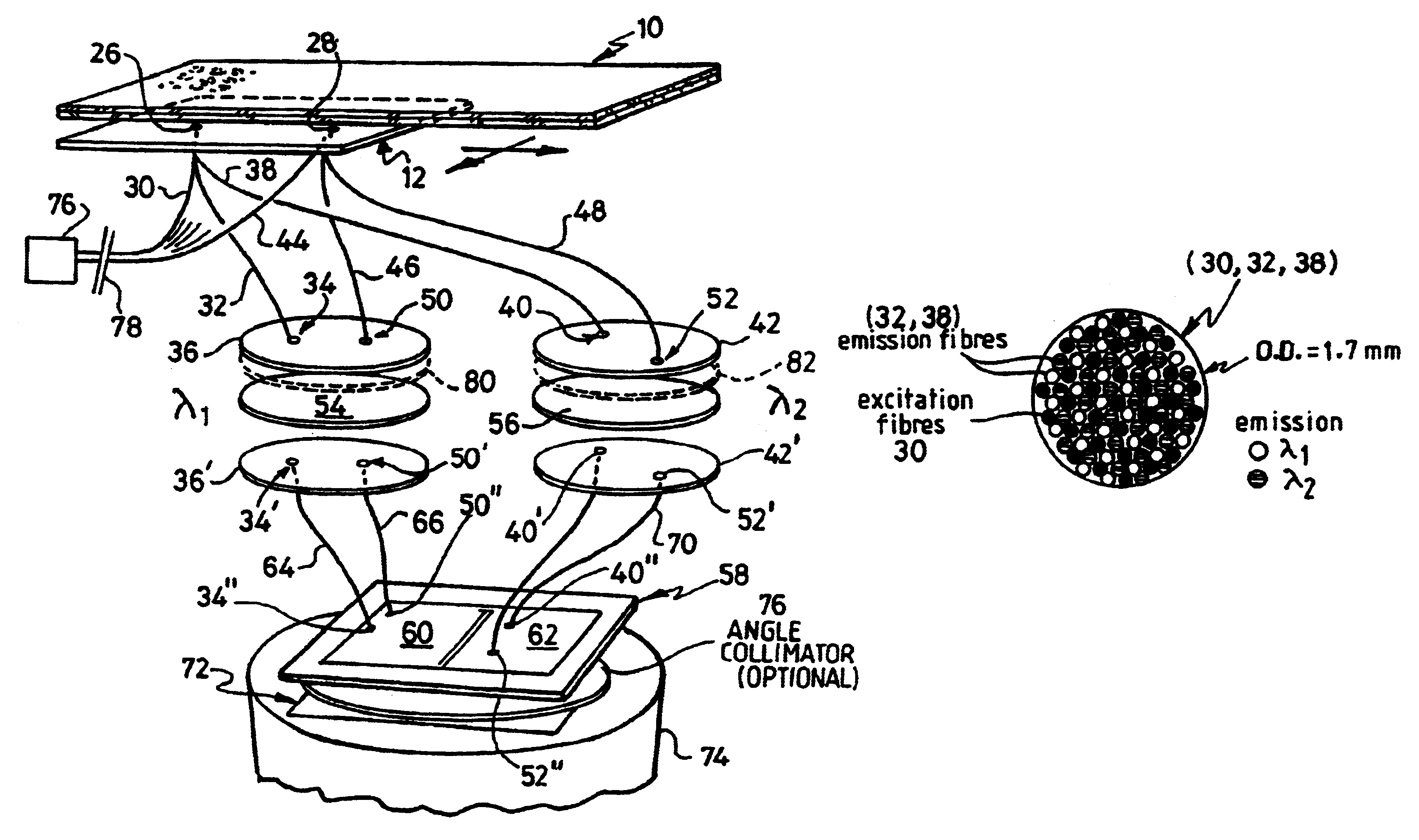
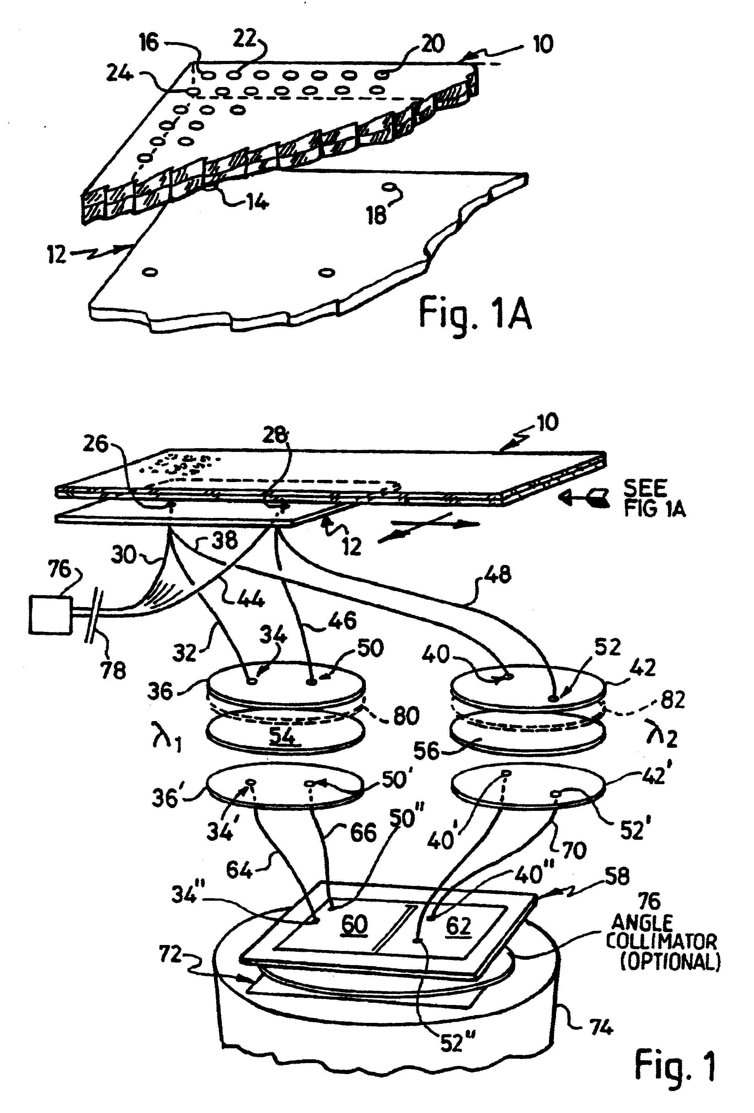
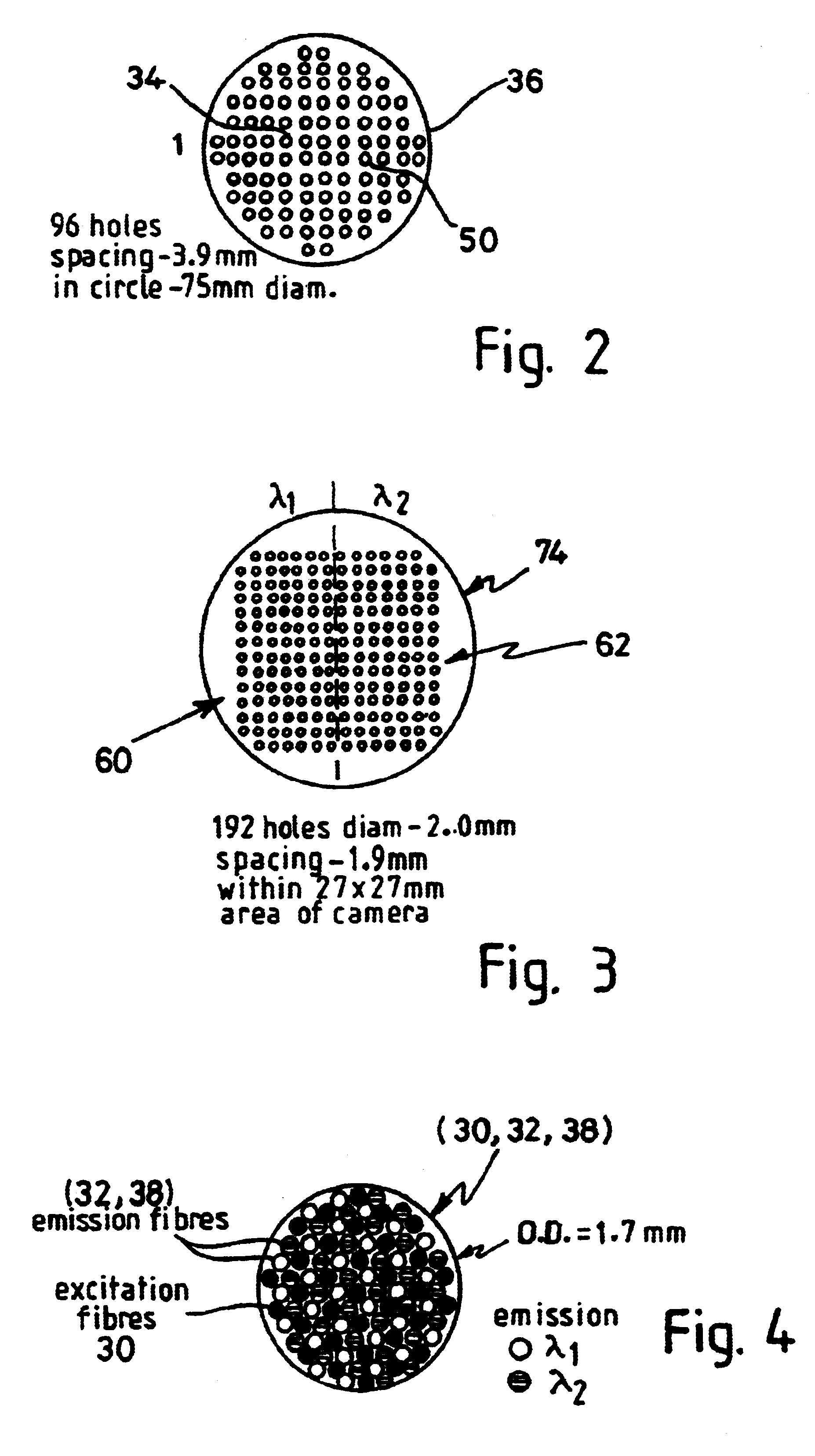
Apparatus for detecting light emitted by assay samples is provided, in which light emitted by the sample is collected for transmission to a charge coupled device camera (74) by an optical fiber bundle. The cross-sectional area of the optical fiber bundle corresponds to the area of the sample, the end of which is located close to the sample for detecting any light emitted therefrom, and selected fibers (30) of those making up the bundle are separated from the remainder and extend to a source of excitation radiation (76) and serve to convey excitation radiation (if required) directly to a corresponding plurality of points distributed over the are of the end face of the bundle and therefore over the area of the sample. The remaining fibers (32, 38) of the bundle serve to collect emitted light (whether generated by fluorescence caused by excitation or otherwise) and provide a light path to the change coupled device camera, wherein the ends of the excitation fibers and the ends of the emitted light collecting fibers area distributed uniformly over the area of the fiber bundle presented to the reaction site.

Description

This invention concerns methods and apparatus for imaging, and particularly the imaging of luminescence samples of the type in which the sample is illuminated with excitation radiation such as ultra-violet light, or where the sample is activated by some suitable chemiluminescent or bioluminescent means, and is interrogated for any resulting emission light due for example to fluorescence within the sample. The invention is particularly concerned with multipath (or multichannel) systems in which a large number of samples can emit light and need to be interrogated at the same time.BACKGROUND TO THE INVENTIONPCT Application No. WO 98 / 0144 describes a fluorescence assay imaging system in which excitation radiation is supplied to the assay sample via an annular sleeve fitted around the end of a fibre optic bundle the end of which is in close proximity to the assay sample. The fibres collect emitted light due to fluorescence induced by the excitation radiation. It has been found that using...

Claims


Application Information

Patent Timeline
Patent Type & Authority Patents(United States)
IPC IPC(8): G01N21/64G01N21/76
CPCG01N21/6452G01N21/76G01N2021/6421G01N2021/6484G01N2201/0826G01N2201/0833G01N2201/0866
Inventor RUSHBROOK, JOHN GORDONHOOPER, CLAIRE ELIZABETH
Owner PEKINELMER SINGAPORE PTE LTD
Learn More