In situ thermal processing of a hydrocarbon containing formation using a controlled heating rate

a hydrocarbon and heating rate technology, applied in the direction of survey, insulation, borehole/well accessories, etc., can solve the problems of inability to economically mine coal formations, inability to meet the needs of economical mining, and inability to meet the needs of economic mining, etc., to achieve the effect of increasing the heating value of the produced synthesis gas

Inactive Publication Date: 2004-06-08
SALAMANDER SOLUTIONS INC
View PDF433 Cites 263 Cited by
  • Summary
  • Abstract
  • Description
  • Claims
  • Application Information

AI Technical Summary

Benefits of technology

A synthesis gas generating fluid (e.g., liquid water, steam, carbon dioxide, air, oxygen, hydrocarbons, and mixtures thereof) may be provided to the formation. For example, the synthesis gas generating fluid mixture may include steam and oxygen. In an embodiment, a synthesis gas generating fluid may include aqueous fluid produced by pyrolysis of at least some hydrocarbons within one or more other portions of the formation. Providing the synthesis gas generating fluid may alternatively include raising a water table of the formation to allow water to flow into it. Synthesis gas generating fluid may also be provided through at least one injection wellbore. The synthesis gas generating fluid will generally react with carbon in the formation to form H.sub.2, water, methane, CO.sub.2, and/or CO. A portion of the carbon dioxide may react with carbon in the formation to generate carbon monoxide. Hydrocarbons such as ethane may be added to a synthesis gas generating fluid. When introduced into the forma...

Problems solved by technology

A significant number of coal formations are, however, not suitable for economical mining.
For example, mining coal from steeply dipping coal seams, from relatively thin coal seams (e.g., less than about 1 meter thick), and/or from deep coal seams may not be economically feasible.
The energy conversion efficiency of burning coal to generate electricity is relatively low, as compared to fuels such as natural gas.
Also, burning coal to generate electricity often generates significant amounts of carbon dioxide, oxides of sulfur, and oxides of nitrogen that are released into the atmosphere.
The quality of oil produced from such retorting may typically be poor, thereby requiring costly upgrading.
Aboveground retorting ma...

Method used


Image

  • In situ thermal processing of a hydrocarbon containing formation using a controlled heating rate
  • In situ thermal processing of a hydrocarbon containing formation using a controlled heating rate
  • In situ thermal processing of a hydrocarbon containing formation using a controlled heating rate

Examples


embodiments of production well 102

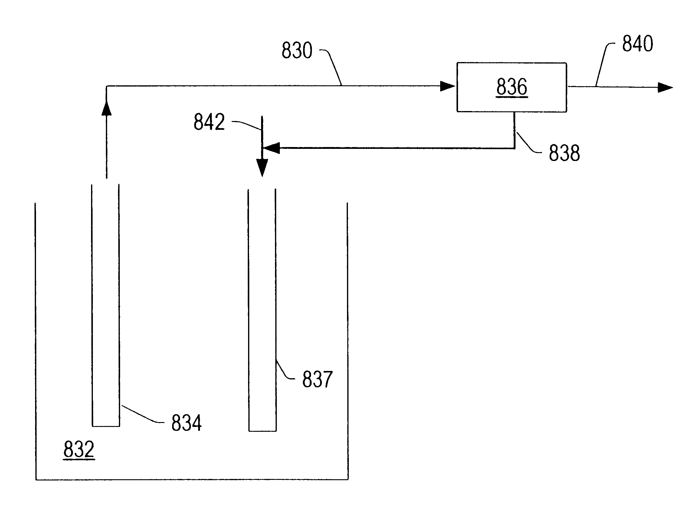
may include valves configured to alter, maintain, and / or control a pressure of at least a portion of the formation. Production wells may be cased wells that may have production screens or perforated casings adjacent to production zones. In addition, the production wells may be surrounded by sand, gravel or other packing material adjacent to production zones. Furthermore, production wells 102 may be coupled to treatment section 108, as shown in FIG. 3. Treatment section 108 may include any of the surface facilities as described herein.

In addition, water pumping wells or vacuum wells may be configured to remove liquid water from a portion of a hydrocarbon containing formation to be heated. Water removed from the formation may be used on the surface, and / or monitored for water quality. For example, a plurality of water wells may surround all or a portion of a formation to be heated. The plurality of water wells may be configured in one or more rings surrounding the portion of the f...


PUM


Abstract

A hydrocarbon containing formation may be treated using an in situ thermal process. A mixture of hydrocarbons, H.sub.2, and/or other formation fluids may be produced from the formation. Heat may be applied to the formation to raise a temperature of a portion of the formation to a pyrolysis temperature. A heating rate to a selected volume of the formation may be controlled by altering an amount of heating energy per day that is provided to the selected volume.

Description

BACKGROUND OF THE INVENTION1. Field of the InventionThe present invention relates generally to methods and systems for production of hydrocarbons, hydrogen, and / or other products from various hydrocarbon containing formations. Certain embodiments relate to in situ conversion of hydrocarbons to produce hydrocarbons, hydrogen, and / or novel product streams from underground hydrocarbon containing formations.2. Description of Related ArtHydrocarbons obtained from subterranean (e.g., sedimentary) formations are often used as energy resources, as feedstocks, and as consumer products. Concerns over depletion of available hydrocarbon resources have led to development of processes for more efficient recovery, processing and / or use of available hydrocarbon resources. In situ processes may be used to remove hydrocarbon materials from subterranean formations. Chemical and / or physical properties of hydrocarbon material within a subterranean formation may need to be changed to allow hydrocarbon ma...

Claims


Application Information

Patent Timeline
IPC IPC(8): C09K8/58C09K8/592E21B36/04E21B43/30E21B43/00E21B43/24E21B43/243E21B43/16E21B43/247E21B41/00E21B36/00
CPCC09K8/592E21B36/001E21B36/04E21B41/0057E21B43/24E21B43/2401E21B43/243E21B43/247E21B43/30Y02C10/14Y10S48/06Y02P20/582Y02C20/40
Inventor WELLINGTON, SCOTT LEEVINEGAR, HAROLD J.DE ROUFFIGNAC, ERIC PIERREBERCHENKO, ILYA EMILSTEGEMEIER, GEORGE LEOZHANG, ETUANSHAHIN, JR., GORDON THOMASFOWLER, THOMAS DAVIDRYAN, ROBERT CHARLES
Owner SALAMANDER SOLUTIONS INC
Why Eureka
Try Eureka