

Laser working method and method for producing ink jet recording head
a working method and ink jet technology, applied in the field of laser working method, can solve the problems of destructing the shape of the workpiece (the object to be worked), difficult to achieve fine work, and destructing the shape of the workpi
- Summary
- Abstract
- Description
- Claims
- Application Information
AI Technical Summary
Benefits of technology
Problems solved by technology
Method used
Image

Examples
example 2
(Example 2)
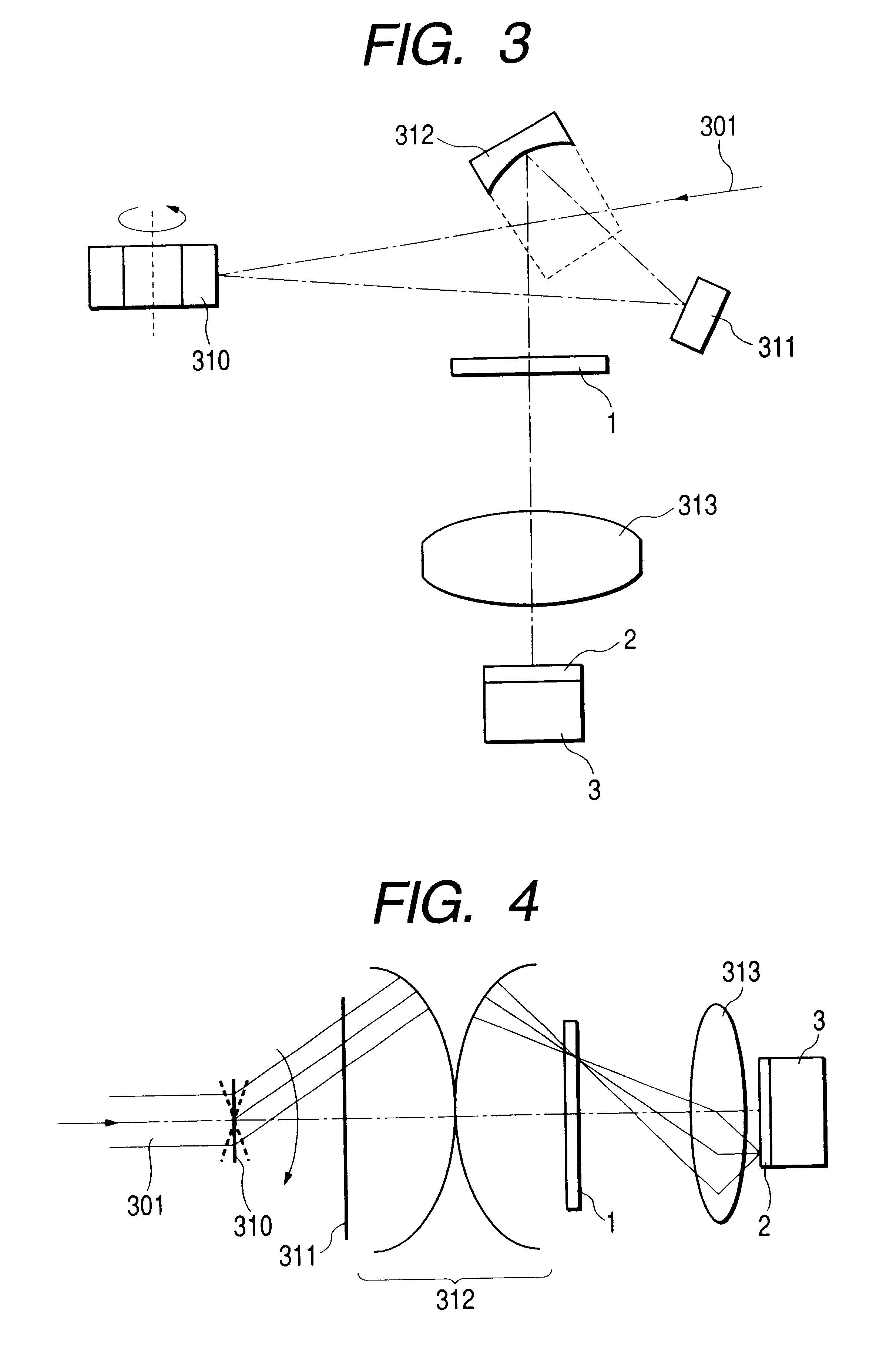
FIG. 3 is a schematic view showing the optical path of a mask pattern projecting optical system of a laser working apparatus in Example 2 of the present invention.
Referring to FIG. 3, a laser beam 301 emitted from an unrepresented laser is guided to a deflecting device 310 including a polygon mirror, wherein the entering laser beam is deflected by the rotary motion, indicated by an arrow, of the polygon mirror. The deflected light beam is reflected by a flat mirror 311 to a concave spherical mirror 312 which reflects and condenses the laser beam substantially on a mask 1, thereby illuminating a mask pattern shown in FIG. 5 by scanning.
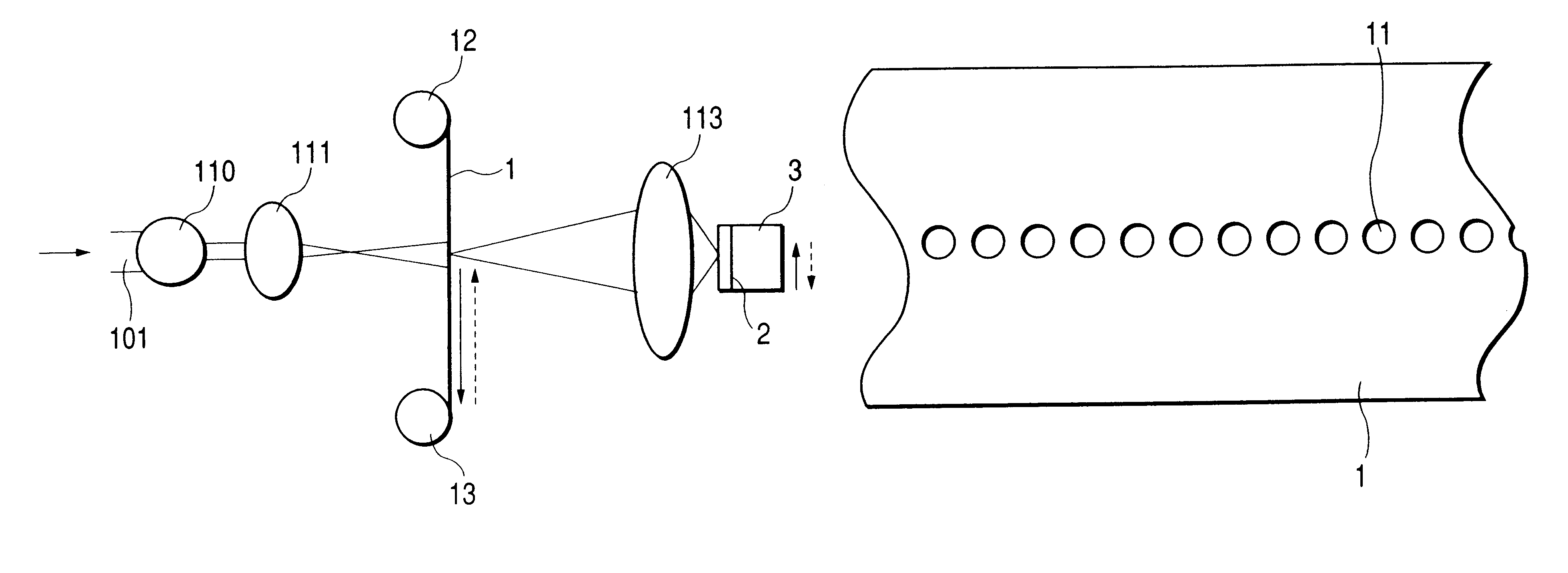
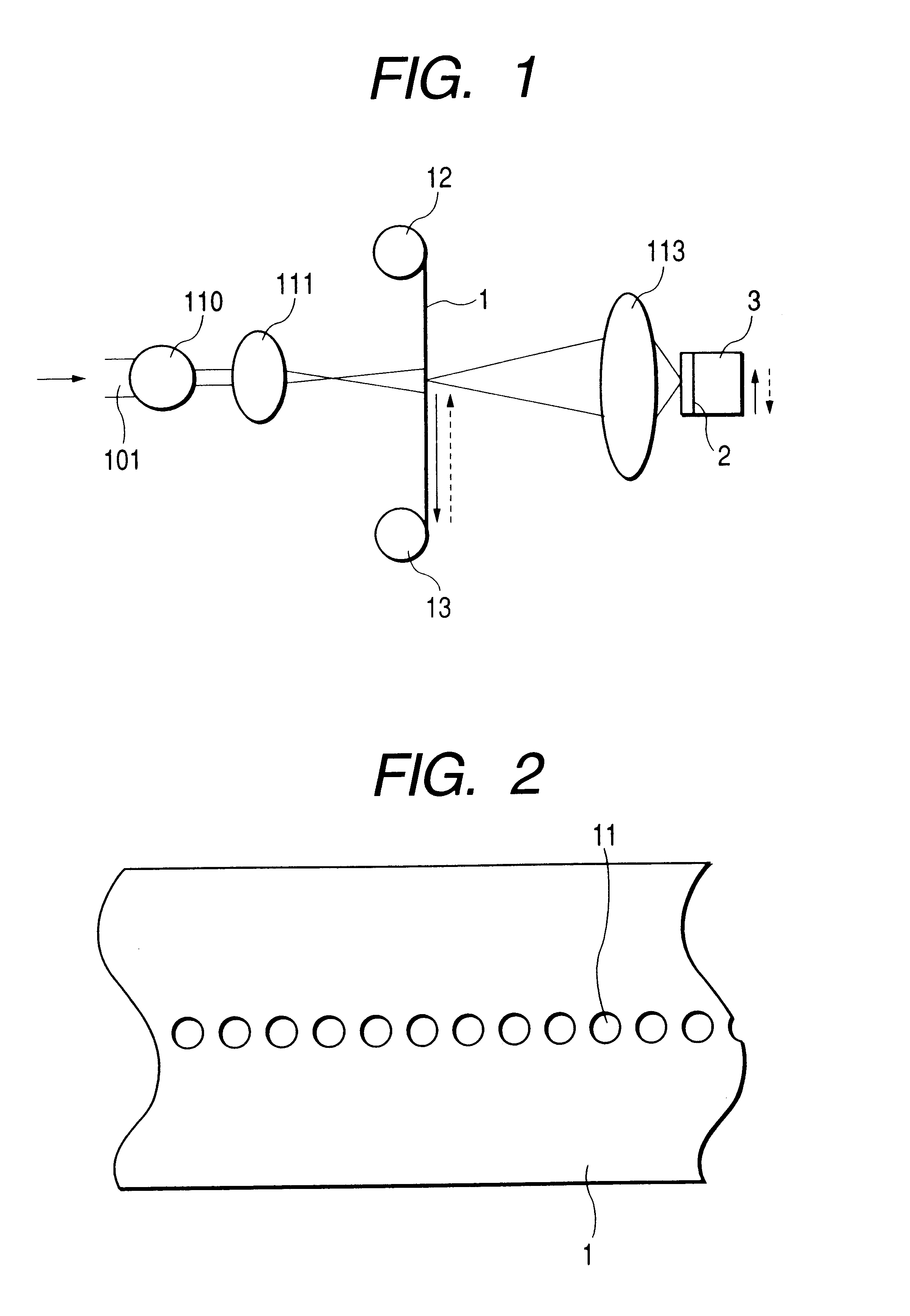
The laser beam transmitted by the mask pattern of the mask 1 is focused and projected by a projection lens 313 onto the surface of an orifice plate 2 of an ink jet head 3 constituting the workpiece, whereby an ink discharge port is formed by laser oscillation. Though there is employed a pulsed laser, the repeated scanning illumination of the...
example 3
(Example 3)
FIG. 6 is a schematic view showing the optical path of a laser working apparatus in Example 3 of the present invention. In the following there will be explained, with reference to FIG. 6, a working method for an ink discharge nozzle of the present Example. Referring to FIG. 6, a laser beam 601 emitted from an unrepresented short-pulsed laser is guided to mutually opposed conical lenses 615 for converting the incident laser beam 601 from a circular beam A into a ring-shaped beam B, as shown in FIG. 7. The ring beam is then guided to a deflecting device 610 including a polygon mirror, wherein the entering laser beam is deflected by the rotary motion, indicated by an arrow, of the polygon mirror. The deflected light beam is reflected by a flat mirror 611 to a concave spherical mirror 612 which reflects and condenses the laser beam substantially on a mask 1, thereby illuminating, by scanning, a mask pattern 11 formed by chromium evaporation and patterning on the mask plate 1 ...
example 4
(Example 4)
FIG. 10 is a view showing a working method for the discharge nozzle in Example 4 of the present invention.
A laser beam 1101 emitted from an unrepresented short-pulsed laser is guided to mutually opposed conical lenses 1115 for converting the incident laser beam 1101 from a circular beam A into a ring-shaped beam B as shown in FIG. 11.
The ring beam is then guided to a deflecting device 1110 including a polygon mirror as shown in FIG. 10, wherein the entering laser beam is deflected by the rotary motion, indicated by an arrow, of the polygon mirror. The deflected light beam is reflected by a flat mirror 1111 to a concave spherical mirror 1112 which reflects and condenses the laser beam substantially on a mask plate 1, thereby illuminating, by scanning, a mask pattern 11 formed by chromium evaporation and pattering on the mask plate 1 as shown in FIG. 5.
The laser beam transmitted by the mask pattern of the mask 1 is focused and projected by a projection lens 1113 onto the su...
PUM
| Property | Measurement | Unit |
|---|---|---|
| Time | aaaaa | aaaaa |
| Time | aaaaa | aaaaa |
| Wavelength | aaaaa | aaaaa |
Abstract
Description
Claims
Application Information