Electrostatic printing of functional toner materials for electronic manufacturing applications

a technology of functional toner and electrostatic printing, which is applied in the field of electrostatic printing of functional materials, can solve the problems of small display (10.4 inch diagonal) for lap top computers, and high and achieves the effect of reducing the cost of modern amlcd production facilities and reducing the cost of production

Inactive Publication Date: 2004-08-24
ELECTROX
View PDF16 Cites 34 Cited by
  • Summary
  • Abstract
  • Description
  • Claims
  • Application Information

AI Technical Summary

Problems solved by technology

Billions of dollars have been spent on their development over the last 20 years, but the results have been only an expensive small display (10.4 inch diagonal) for lap top computers.
Wall type TV units, 20" diagonal or so, are perhaps available after the year 2000, but very expensive.
There is "suite" of expensive capital equipment in a typical $500 per square foot clean room so that the cost of a modern AMLCD production facility is approximately $500 Million.
None of the raw materials for the displays, including the glass, glass powder or frit, phosphor, aluminum or nickel, resin or color filter resins are very expensive.
Costs are incurred by the capital equipment and low yield of a complex process with many steps.
Such plates when imaged by simple conditions will develop out the large image features but small image detail or fine structures are lost.
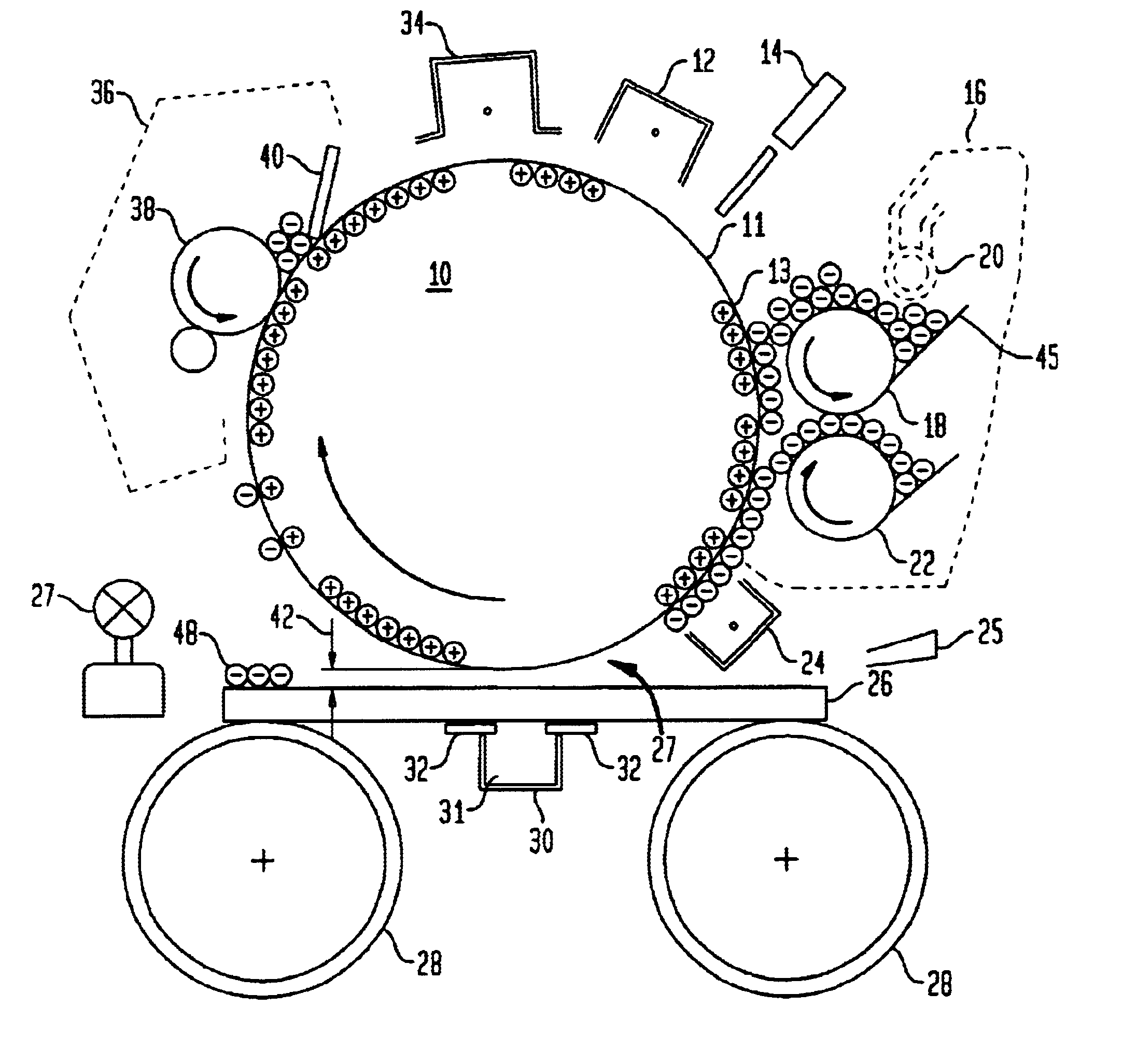
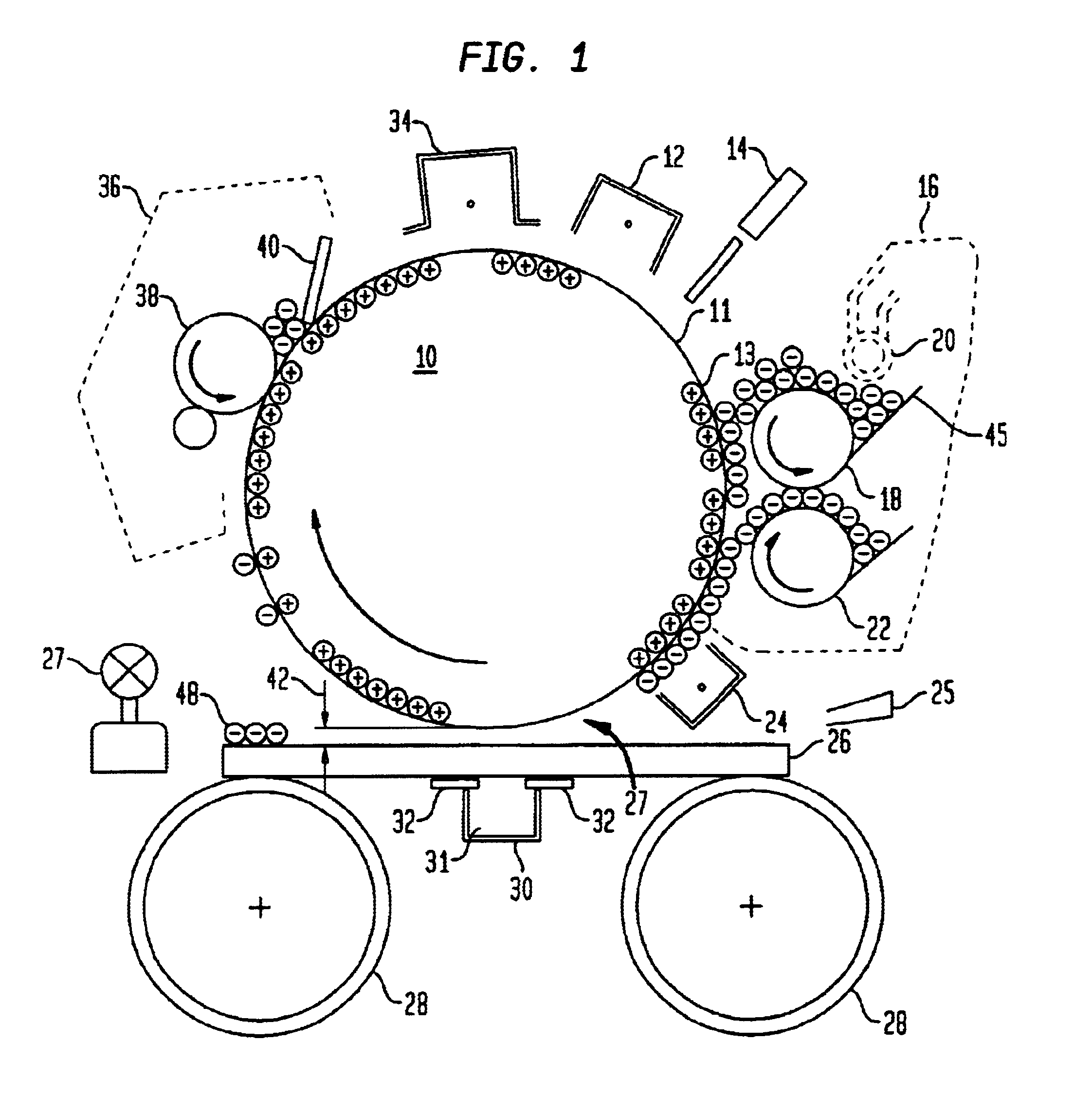
The electrostatic printing plate poses new problems for corona design.
This was important otherwise the drum voltage, if excessive, could puncture the photo conductive surface of the drums used at that time, causing permanent damage.
One problem with the simple corona unit is that in the negative mode the corona discharge is not positionally stable but moves back and forth randomly.
One unfo

Method used


Image

  • Electrostatic printing of functional toner materials for electronic manufacturing applications
  • Electrostatic printing of functional toner materials for electronic manufacturing applications
  • Electrostatic printing of functional toner materials for electronic manufacturing applications

Examples


second alternate embodiment

FIG. 12 shows a cross section of the cathode plate 200 of an AC Plasma Color Display Panel. It consists of a glass back plate 201 with black glass spacer ribs 202 that optically and electrically isolated image cells from one another. These ribs are typically 100.mu. high and 30.mu. to 40.mu. in nominal width. At the bottom of the "wells" are the address electrode lines of copper 204 or nickel metal. Covering the walls and bottom of the "canyons" is the phosphor 206 that converts the UV radiation from the plasma discharge to visible radiation, RG&B in the case of a color display. Alternate canyons are coated with red, then green then blue phosphor.

One advantage of the electrostatic printing technique is the non-contact or gap transfer aspect of it; i.e. the ability to transfer functional materials across relatively large mechanical gaps.

FIG. 13 is a greatly magnified picture of the mechanical gap 220 between the print drum and glass surface 200 of the invention. The gap here is set t...

third alternative embodiment

An alternate method to produce conductors is to print metal toners themselves, to bum off the resin that coats the metal particles; then reflow the metal into a smooth conductor pattern. Using the invention of the preferred embodiment one prints an aluminum toner onto the glass. The toner is then dried to temporarily fix it for reasons of safe handling. Now a rapid thermal processing of the metal is effected, where the toner and glass is raised to a temperature of 50.degree. to 100.degree. C. below the softening point of the glass (approximately 500.degree. C. for soda lime glass). This effectively bums off the resin that coats the metallic particles. Now with an intense UV light source, the aluminum is heated to its melting point while the glass absorbs little UV energy. Aluminum which melts at 659.degree. C. is a good choice of materials to be used with soda lime glass. Note this is not done in air but in a "reducing" atmosphere like one used in aluminum welding work.

fourth alternate embodiment

In this embodiment the glass 300 in FIG. 14a is first coated with a thin, transparent layer 301 that is electrically conductive. This very thin layer is not shown. Indium Tin Oxide (ITO) is a possibility except it absorbs about 5 to 10% of the transmitted light and ITO processing is expensive, of the order of $5 per square foot. The ITO conductivity of 50 to 100 ohms per square for a typical 2.mu. thick layer is higher than needed for this electrostatic process. A conducting polymer as resistive as 10.sup.+5 ohms per square is adequate for this electrostatic process, all that is needed is to establish an electrostatic ground plane 302 as shown in FIG. 14a.

In this case the coated glass 300 is imaged with the RGB color mosaics 304 which are then reflowed by final heating. The plate is now complete except for the black intermatrix which has yet to be produced. Transparent conductive layer is electrically grounded through edge contact 306 as shown in FIG. 14a. Now the entire plate is co...


PUM


Abstract

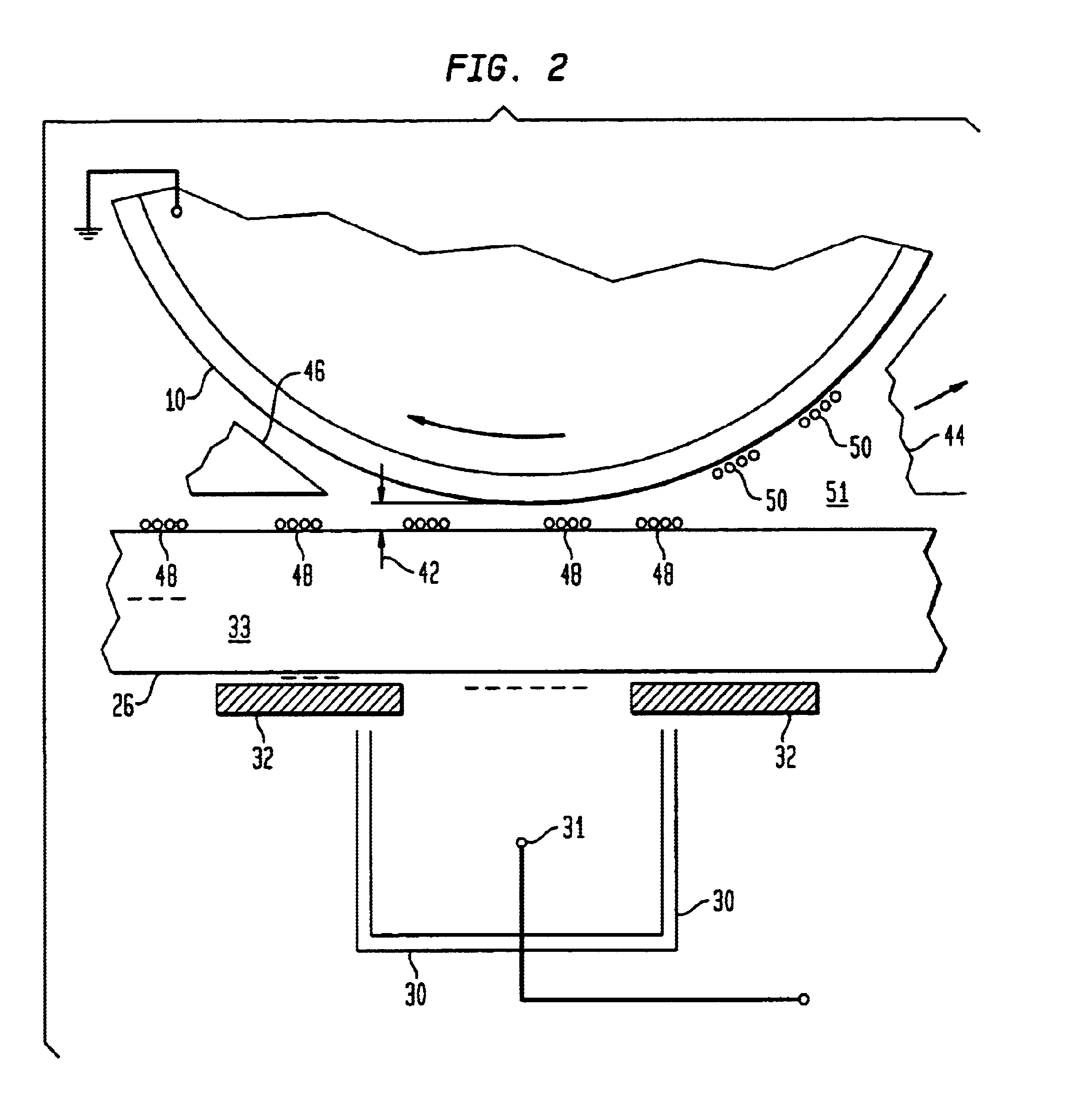
The invention describes techniques for the electrostatic printing of functional materials configured as liquid toners (45) on glass substrates (26) in a non-contact mode. The toners are patterned by a sensitized electrostatic printing plate (11) of fixed image configuration. Toner images (50) are transferred by an electric field (33) across a fluid filled mechanical gap (42) to the glass substrate (26). Techniques for optimizing the imaging and transfer processes are also disclosed. Two other techniques in which partially finished pieces are manipulated to "self-part" themselves, are described. In both cases defects in the pieces will over print the defect in the "self-healing" mode.

Description

1. Field of the InventionThe invention concerns a process for the electrostatic printing of functional materials configured as liquid toners on relatively thick glass plates for various manufacturing applications.2. Description of the Related ArtFlat panel displays or wall type television sets have been discussed in the prior art literature for about forty years, but few have been produced. As of mid 1998 there were three primary flat panel technologies for flat panel displays:a. Field Emission Displays (FED's.)b. Plasma Displaysc. Active Matrix Liquid Crystal Displays (AMLCD)Field emission displays are a relatively new technology. They consist of an array of field emission points in a vacuum, spraying electrons onto a phosphor screen. With three color dots on the screen and addressibility of the emitting points, one has a full color display.The Plasma displays have been produced for about 25 years, mostly as a single color orange neon "glow discharge". In the last 10 years, UV ligh...

Claims


Application Information

Patent Timeline
IPC IPC(8): B41J2/447G03G15/16G03G15/10
CPCB41J2/4476G03G15/10G03G15/1625G03G2215/0626
Inventor DETIG, ROBERT H.
Owner ELECTROX
Why Eureka
Try Eureka