The tether layer is disposed from one elastic member to the other (or joins two elastic members) in order to maintain the relative position of the two members during release. If the structure includes more than two elastic members, the tether layer may extend across or join all members. While in general, for multiple elastic members, a single tether extending across all of the elastic members may be easiest to deposit and pattern, it should be noted that a tether need only join adjacent elastic members, i.e., a plurality of individual tethers, one for each adjacent pair of elastic members, may also be used. Generally, the tether layer will be approximately perpendicular to the length of the elastic members, but may be placed on a
diagonal. More than one tether layer may be used for lengthy elastic members. In one embodiment, the elastic members are formed of an
electrically conductive material and the tether layer is formed of a non-conductive material. After release and any subsequent
processing steps, the tether
layers may be removed or remain intact. This embodiment may be easily combined with one or more of the other embodiments described below.
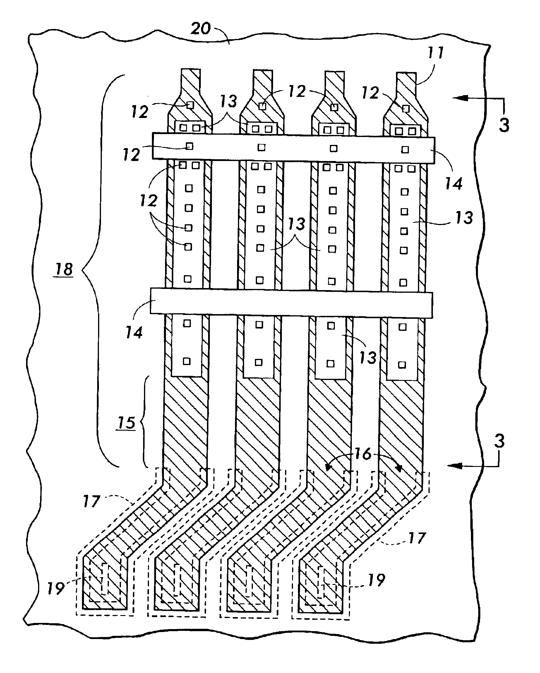
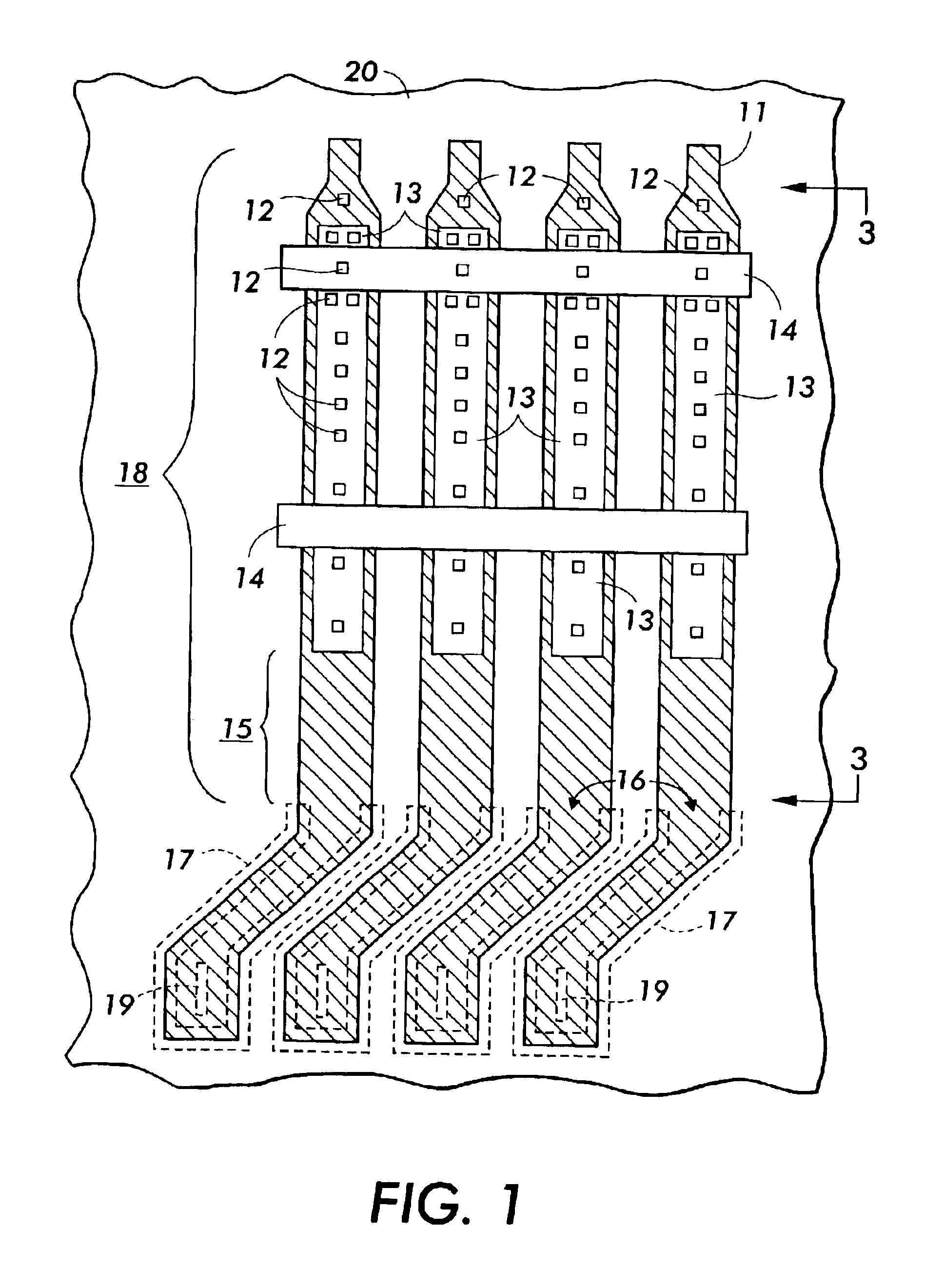
By placing one or more tethers joining the elastic members prior to release, the floppiness problem of very long flexible released elastic members is essentially eliminated. The tethers on the elastic members release along with the elastic members, and maintain spacing and separation of the individual released elastic members. The tethers may be made sufficiently narrow or perforated to ensure that the release etch releases the tethers along with the released elastic members (to promote release, if the released elastic members are perforated, the perforations will generally extend through to the release layer). The tethers maintain uniform array spacing and prevent the released elastic members from touching or entangling. The ensemble of tethered released elastic members behaves like an effectively stiffer structure. The tethers actually constrain the undesired flexures of the released elastic members relative to one another, while leaving the
curling behavior of the released elastic members largely unchanged. There can be a loading effect due to the tether that effectively changes the
radius of the released elastic member relative to what it would be without the tether. Design considerations can allow for this effect.
The tether structure has utility anywhere that a floppy out-of-plane structure would otherwise suffer from unconstrained flexure, including applications for coils and out-of-plane spring cantilevers such as
flip chip packages and probe cards. For example, tethers can be used to hold the springs in uniform registration during release and a subsequent plating step that substantially stiffens the structures.
Perforations in the material of the elastic member allow etchant to have greater access to the interior portions of the member segment, and thereby allow the elastic member to release faster with less
undercut etching at the member base. By grading the perforation density, or having the perforations unequally spaced along the member, the elastic member then releases from the substrate in a controlled fashion starting with the tip or free end, and progressing toward the base or anchor portion. This can be important because of the large amount of
elastic energy that is stored in the elastic member. If the release rate of the energy is too rapid, the elastic member can reach enough speed to entangle with other elastic members or break. Gradual,
controlled release of the elastic member allows mechanical damping enough time to limit the total
kinetic energy of the elastic member to a non-destructive level.
Controlling the
radius of curvature in both spring structures and coil structures is often required by design considerations. One of the ways of controlling the
radius of curvature of the coil structures is to deposit a load layer on the elastic member prior to release of the elastic member. In accordance with another embodiment of the invention, further control can be achieved by depositing the load layer using a reflow material, i.e., any material that softens at a process compatible temperature. An example of a suitable reflow material is
photoresist, but other suitable reflow materials may also be used. The load layer of reflow material can be introduced in the same masking step that creates the release window, or it can be introduced in a separate step. One desirable feature of using a
photoresist load layer is that the loading effect of the
resist can be gradually changed with heat and
clean up is easily accomplished with
plasma ashing.
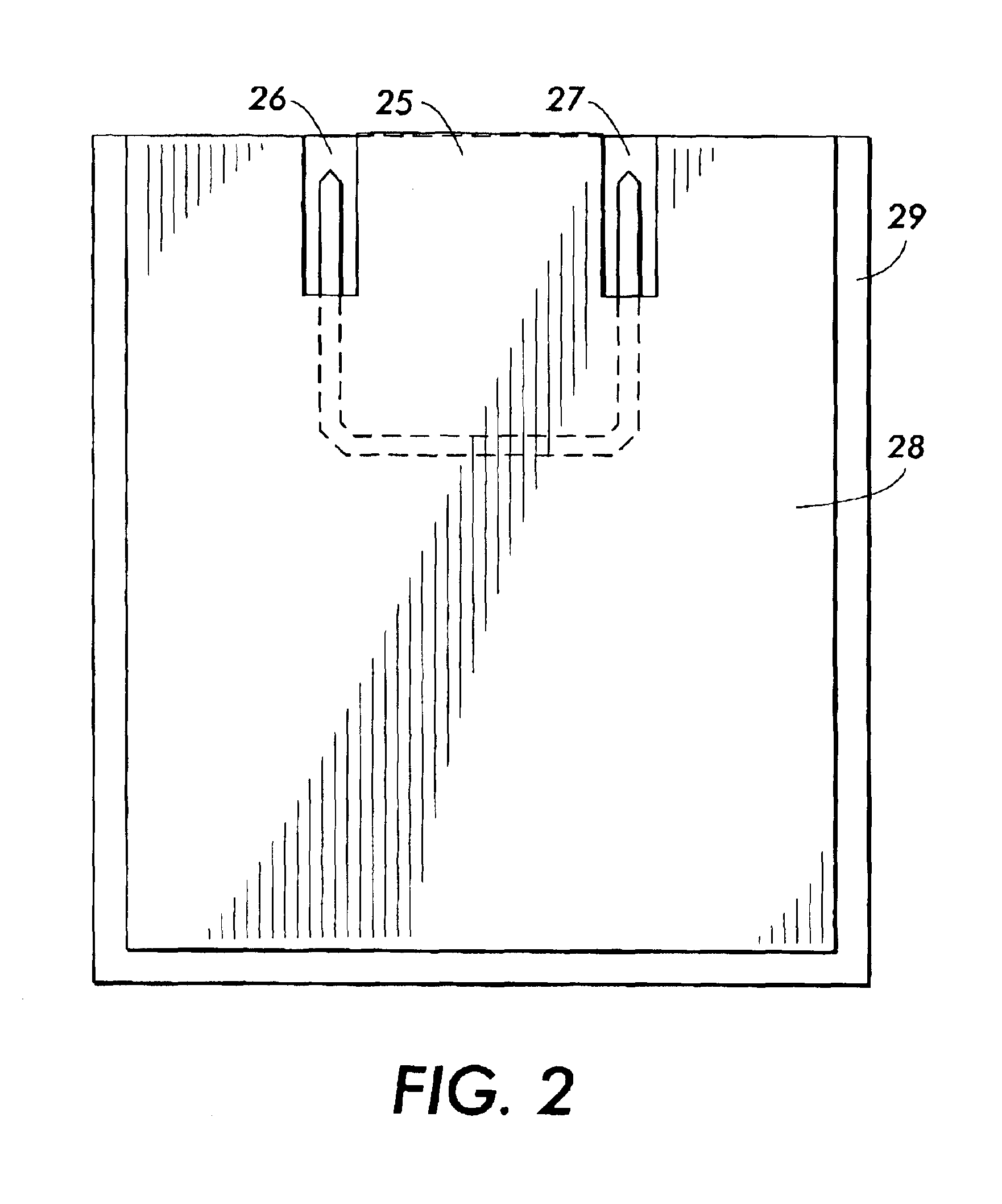
In accordance with another embodiment of the invention, an out-of-plane
coil structure, may be formed by joining two elastic members in mid-air. To facilitate latching of the two elastic members, one free end includes an elongated tip and the other free end includes a tip having a groove for receiving the elongated tip. The two free ends can be easily connected by
soldering or plating.

