Hydrophilic zeolite coating

a technology of zeolite and zeolite, which is applied in the direction of physical/chemical process catalysts, other chemical processes, lighting and heating apparatus, etc., can solve the problems of reducing the performance of the condensing heat exchanger, increasing air pressure drop, and micro-gravity environment of spa

Inactive Publication Date: 2005-02-01
HONEYWELL INT INC
View PDF33 Cites 18 Cited by
  • Summary
  • Abstract
  • Description
  • Claims
  • Application Information

AI Technical Summary

Problems solved by technology

Water droplets, if allowed to form, can cause problems in the micro-gravity environment of space.
If strongly attached to the heat transfer surfaces, the water droplets may cause an increase in air pressure drop across the condensing heat exchanger and, consequently, a reduction in performance of the condensing heat exchanger.
In such instance, rain could quite literally fall inside the cabin.
However, since the hydrophilic coating becomes wet during the operation of the condensing heat exchanger, the moisture provides a potential breeding ground for microbes such as bacteria and fungi.
The microbial growths could block air passages inside the condensing heat exchanger and, consequently, reduce performance of the condensing heat exchanger.
Nevertheless, aluminum is still commonly used because it has high heat conductance and is light in weight.
These coatings, however, do not appear to also be corrosion resistant.
While corrosion resistant, no mechanism is described to make the coating anti-microbial.
However, such pre-coating methodology tends to have a negative impact on process efficiency since components are first coated and then assembled, as opposed to coating an assembled apparatus.
Notwithstanding the advantages provided in the above prior art, disadvantages still remain.
Consequently, compromises have to be made, resulting in non-optimal p

Method used


Image

  • Hydrophilic zeolite coating
  • Hydrophilic zeolite coating

Examples


examples

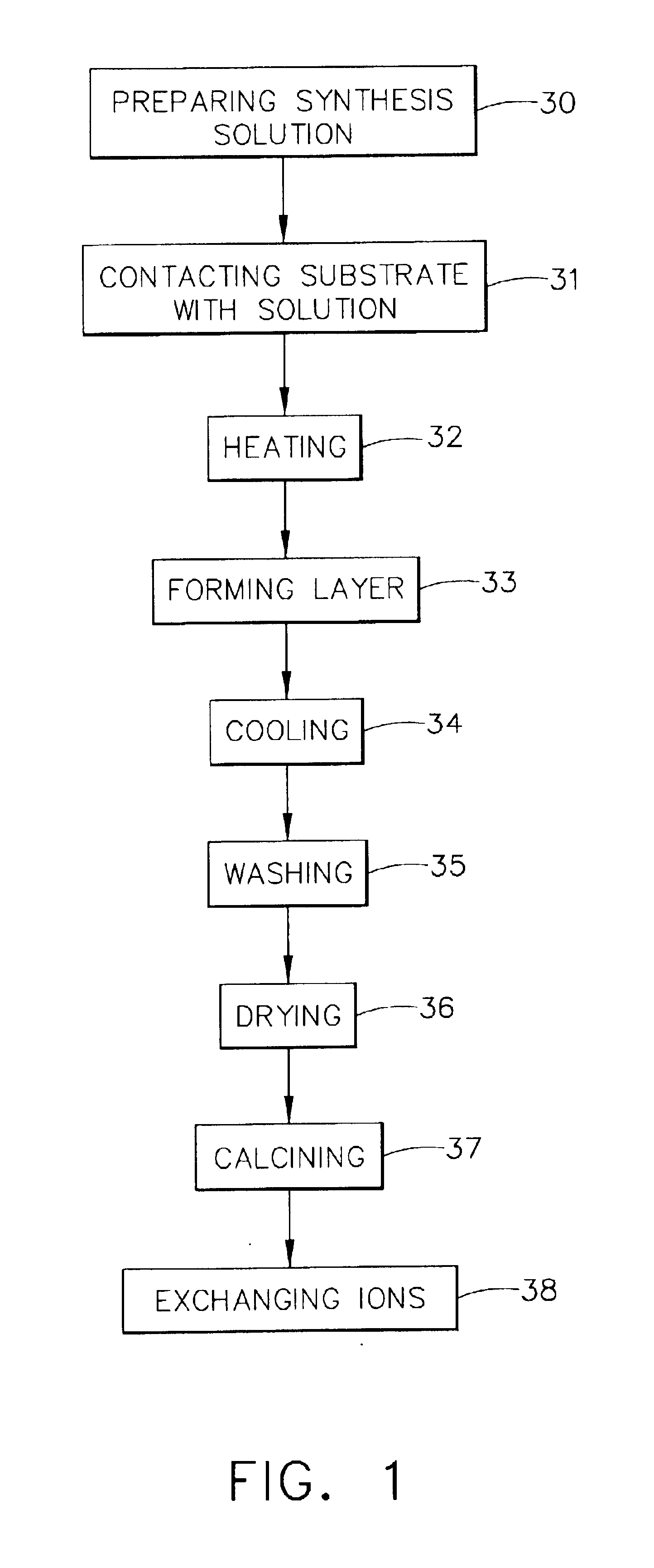
Samples of aluminum alloy 6000 series, stainless steel 347, and nickel were tested. Most of the samples were 1×3″ coupons and the autoclaves used were Parr 45 mL bombs. For the synthesis solution, TEOS (98% liquid), aluminum foil (99.98%), NaOH (50 wt. %), and TPAOH (1M solution) were obtained from Aldrich. Deionized water was also used.

Various synthesis solutions were tested and the following is one preferred solution in which aluminum was included. Aluminum foil (0.0035 grams) was dissolved into 3.6 grams of a 50 wt. % aqueous solution of NaOH. TPAOH (13.35 grams) and water (121.02 grams) were added. The solution was then stirred for 10 minutes and then 16.25 grams of TEOS was added dropwise while stirring. The solution became clear after about 1.5 hours and was further stirred for 4 hours to provide the final synthesis solution.

The synthesis solution was placed into a Teflon lined Parr autoclave and each of the three samples was separately inserted into the autoclave. The substra...


PUM

PropertyMeasurementUnit
Lengthaaaaaaaaaa
Structureaaaaaaaaaa
Electrical resistanceaaaaaaaaaa

Abstract

A hydrophilic coating can be optionally corrosion resistant and/or microbial resistant for a substrate such as a heat exchanger. The coating is provided by a zeolite layer that can be formed from a synthesis solution comprising a structure directing agent, a base, a silicon source, an aluminum source, and a solvent. In one preferred embodiment, the synthesis solution comprises tetrapropylammonium hydroxide, sodium hydroxide, aluminum oxide, tetraethylorthosilicate, and water. The layer is characterized by a zeolite MFI structure and by a composition having the formula of Mn/m[AlnSi(96-n)O192], or [AlnSi(96-n)O192].4[(CH3CH2CH2)4N—OH] wherein M is a metal ion of valence m+ (e.g., Na+) and 27>n>=0. After formation of the coating, the organic structure directing agent can be left intact inside the zeolite coating to make the coating corrosion resistant. Alternatively, and after removal of the organic structure directing agent, a biocidal metal ion can be incorporated into the coating by an ion exchange process to render the coating microbial resistant. A hydrophilic coating that is also corrosion resistant and microbial resistant can be made by a zeolite coating with two sub-layers—the bottom sub-layer being corrosion resistant and the top sub-layer being microbial resistant.

Description

BACKGROUND OF THE INVENTIONThe present invention generally relates to hydrophilic coatings. More specifically, the present invention relates to hydrophilic coatings for heat exchanger surfaces and which coatings can also be anti-microbial and corrosion resistant in nature.An environmental control system for a manned spacecraft typically includes a condensing heat exchanger for controlling cabin temperature and humidity. Cabin air is drawn into the condensing heat exchanger and circulated through air passageways. Heat drawn from the drawn-in air is transferred to a coolant that is circulated through coolant passageways within the condensing heat exchanger. As the drawn-in air is being cooled, condensate forms on the heat transfer surfaces of the air passageways. Water droplets, if allowed to form, can cause problems in the micro-gravity environment of space. If strongly attached to the heat transfer surfaces, the water droplets may cause an increase in air pressure drop across the co...

Claims


Application Information

Patent Timeline
IPC IPC(8): B01J29/04B01J29/00F28F13/00F28F13/04F28F19/00F28F19/02F28F13/18
CPCB01J29/04F28F19/02F28F13/182B01J2229/66F28F2265/20F28F2245/02C23C18/1212C23C18/1241
Inventor YAN, YUSHAN
Owner HONEYWELL INT INC
Why Eureka
Try Eureka