Control system for a wind power plant

a control system and wind power technology, applied in mechanical power/torque control, variable speed operation control, wind energy generation, etc., can solve the problems of safety margins being utilized, considerable safety margins of power output left unused in the turbine, etc., to reduce power output, increase component fatigue, and high ratio

Inactive Publication Date: 2005-02-01
GENERAL ELECTRIC CO
View PDF3 Cites 92 Cited by
  • Summary
  • Abstract
  • Description
  • Claims
  • Application Information

AI Technical Summary

Benefits of technology

The above outlined known approach of reducing the power output in case of high wind velocities makes it possible—e.g. in a variable-speed pitch plant with a control algorithm for controlling the rotor speed on the basis of the pitch angle averaged over time to obtain very high ratios between the rotor diameter and the generator performance without an accompanying increase of component fatigue as compared to conventionally designed turbines. A rating of 330 to 280 W / m2 can be obtained and is economically reasonable especially at inland locations.
For reasons of safety, the design of the towers of wind power plants is on principle determined on the basis of very unfavorable assumptions (e.g. high wind turbulences and maximum wind distribution in the designed wind zone); therefore, in the majority of locations, considerable safety margins of the power output are left unused in the turbines. Thus, the problem exists how these normally existing safety margins can be utilized for improving the efficiency of the turbine.

Problems solved by technology

For reasons of safety, the design of the towers of wind power plants is on principle determined on the basis of very unfavorable assumptions (e.g. high wind turbulences and maximum wind distribution in the designed wind zone); therefore, in the majority of locations, considerable safety margins of the power output are left unused in the turbines.
Thus, the problem exists how these normally existing safety margins can be utilized for improving the efficiency of the turbine.

Method used


Image

  • Control system for a wind power plant
  • Control system for a wind power plant

Examples


Embodiment Construction

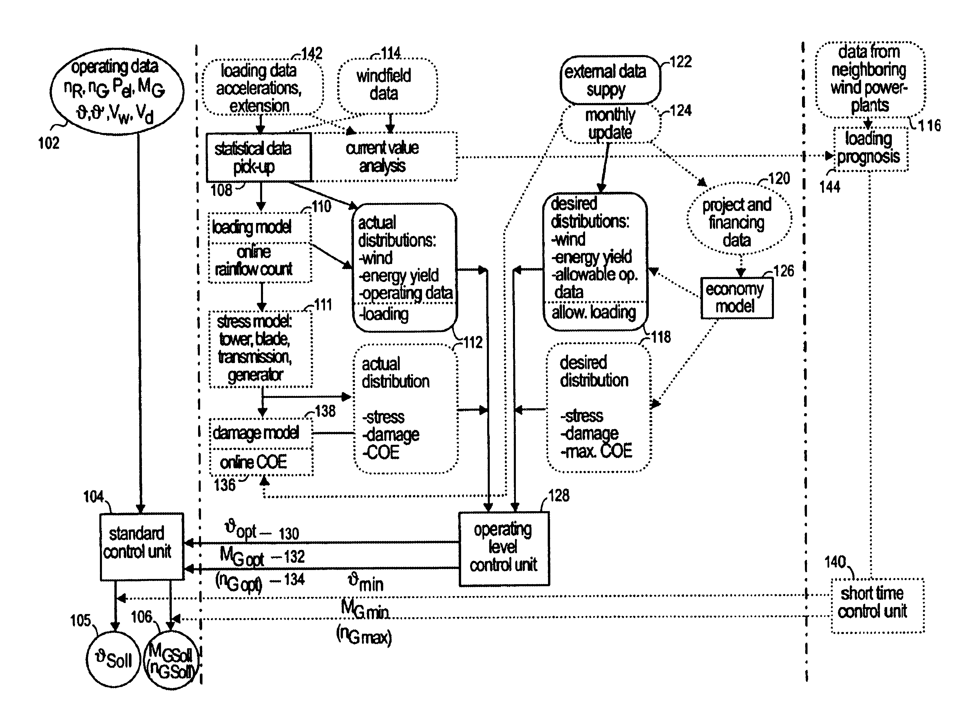
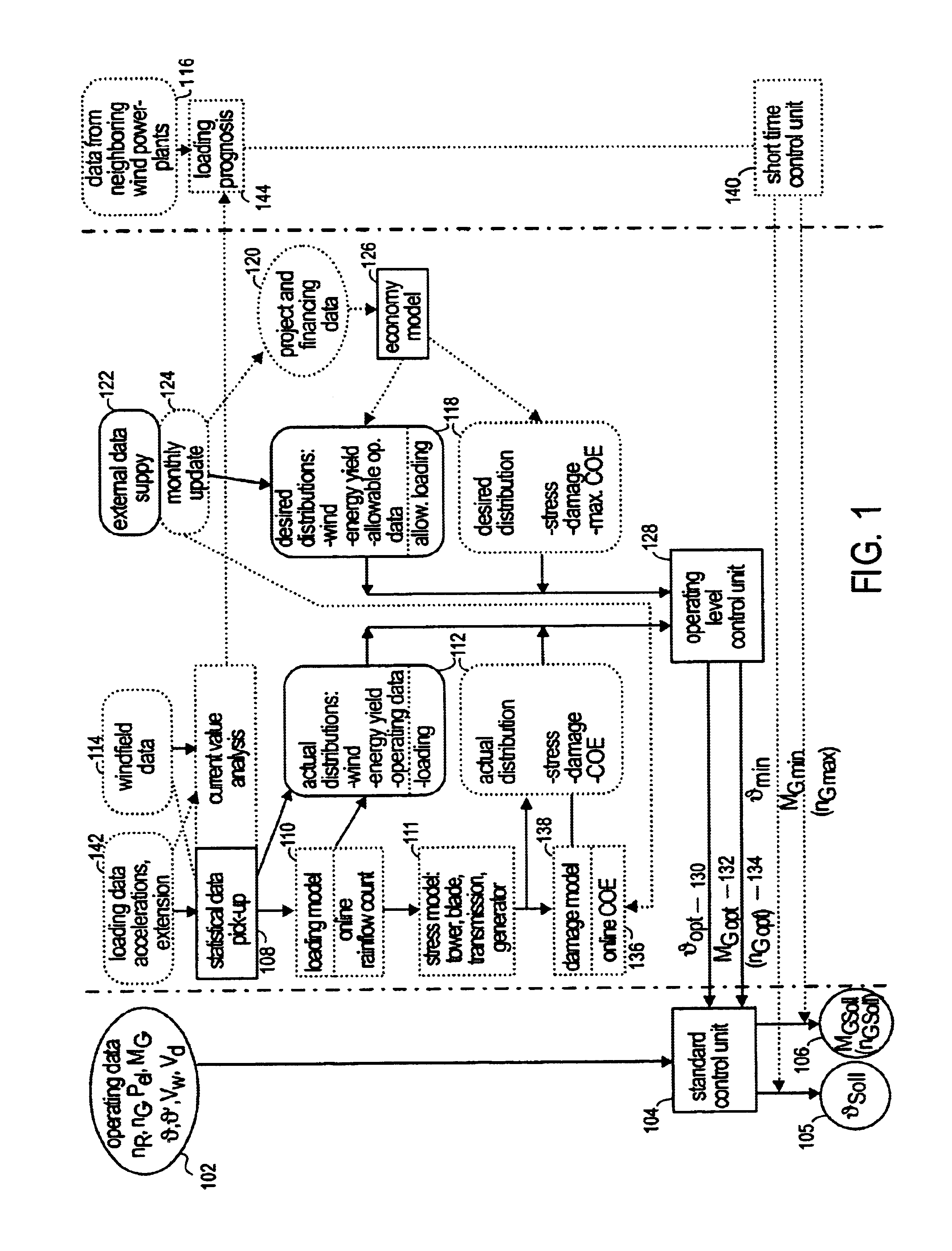
In the block diagram, angular boxes are meant to represent signal processing systems or computing modules of a larger software package installed in a signal processing system. Laterally rounded boxes represent input data for the control system, irrespective of whether these data are measured on the turbine or supplied from an external source. Boxes curved on top and bottom represent data stores containing all data which are required for the execution of the control algorithm and are made available through the internal data detection or analysis, or are supplied from external data sources. Elements represented in solid lines are absolutely required for the control system; elements represented in dotted lines are optional components which improve the function of the control system and thus allow for a higher energy yield even though they will cause an increasing complexity of the control concept. Schematically shown to the left of the vertical dash-dotted line in the left: half of the...


PUM


Abstract

A control system for a wind power plant that includes a damage module and a control module. The damage module compares existing stress conditions on one or more component parts of the wind power plant to current energy generating costs. The control module alters electric power generated by the wind power plant based upon the comparison.

Description

The present invention relates to a control system for improving the efficiency of wind power plants.BACKGROUND OF THE INVENTIONThe annual energy output to be obtained by a wind turbine decisively depends, apart from the performance of the generator as installed, on the rotor diameter. Thus, for increasing the efficiency, it is desirable to use rotors of the largest possible size. However, when enlarging the rotor diameter while otherwise operating the plant under the same conditions, difficulties arise because the stresses acting on the rotor, the nacelle, the tower and the foundation will increase at least by the second power of diameter. Presently usual ratios between the performance of the generator as installed and the rotor area (rating) are in a range from 460 to 330 W / m2, the latter value pertaining to pitch-regulated turbines optimized for inland use.According to an approach frequently used in wind energy technology, an existing turbine to be used in sites with weak winds ca...

Claims


Application Information

Patent Timeline
Patent Type & Authority Patents(United States)
IPC IPC(8): F03D7/04F03D7/00
CPCF03D7/0276F03D7/0292F03D7/042F03D7/043F03D7/048F05B2260/821Y02E10/723F05B2270/20F05B2270/32F05B2270/322F05B2270/331F05B2270/332F05B2270/504F05B2270/1016Y02E10/72
Inventor WEITKAMP, ROLAND
Owner GENERAL ELECTRIC CO
Why Eureka
Try Eureka