Fluid dispense verification system

a verification system and fluid dispense technology, applied in the field of fluid dispense verification system, can solve the problems of reducing the overall size affecting the accuracy of the fluid delivery probe, etc., and achieves the effect of small overall size and simple construction

Inactive Publication Date: 2005-02-08
GEN PROBE INC
View PDF101 Cites 27 Cited by
  • Summary
  • Abstract
  • Description
  • Claims
  • Application Information

AI Technical Summary

Benefits of technology

Having two electrodes, longitudinally spaced from each other and forming portions of the fluid delivery probe conduit, the sensor of the present invention is simple in construction and unobtrusive and adds little to the overall size of the fluid delivery probe. Moreover, the sensor does not suffer from the deficiencies encountered wit

Problems solved by technology

Clinicians especially prefer automated analyzers over manual procedures because of their high-throughput capabilities, reduced labor expenses, and the limits they place on human error that can lead to false or misleading results.
If a voltage is applied across the electrodes the electrical coupling caused by the electrodes contacting the fluid surface results in a measurable change in the voltage drop across the electrodes.
For example, achieving adequate accuracy and repeatability with capacitive surface sensors can be difficult because the change in capacitance exhibited when a probe contacts a fluid surface can be very small and thus difficult to detect.
Furthermore, because of the small capacitance changes exhibited, capacitive surface detection sensors can be susceptible to inaccuracies due to fluctuating stray capacitances caused by adjacent moving structures or changes in the amount of fluid contained in the probe and/or container.
Dual electrode surface detection devices constructed to date, with side-by-side or coaxial arrangement of the electrodes, are complex and cumbersome.
Surface detection devices that emit constant pressure gas can cause disturbances and even bubbling and/or atomization of the fluid.
The effectiveness of optic sensors can be diminished due to residue or other buildup on the optic emitter and/or receiver.
Such fluid flow verification devices suffer from shortcomings which can limit their effectiveness.
Pressure sensors that measure the amount of pressure required to hold up a column of aspirated fluid may be effective for confirming a proper aspira

Method used


Image

  • Fluid dispense verification system
  • Fluid dispense verification system
  • Fluid dispense verification system

Examples


Embodiment Construction

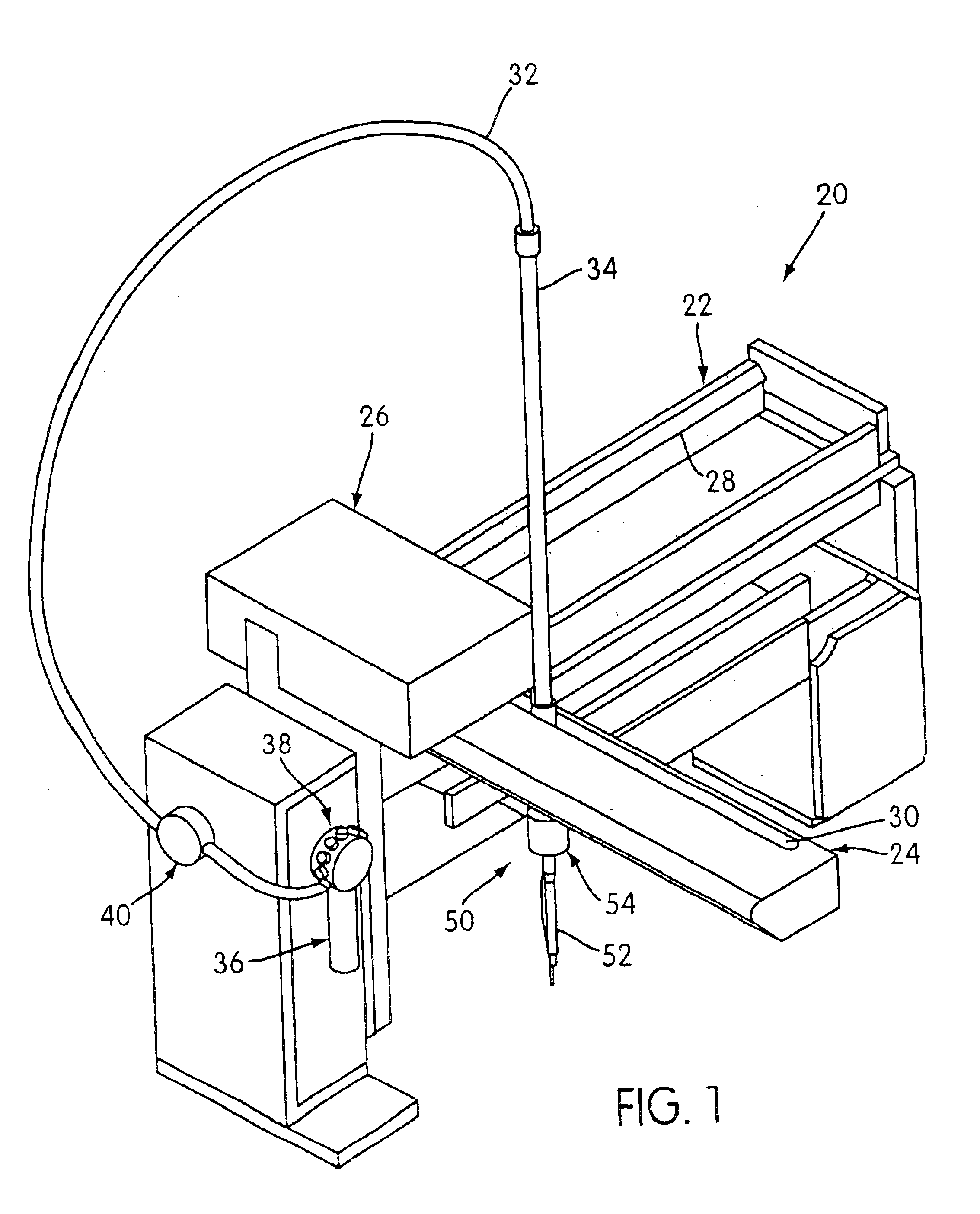
A robotic substance transfer mechanism with which a fluid dispense and fluid surface verification system according to the present invention can be operationally combined is generally designated by reference number 20 in FIG. 1. The robotic substance transfer mechanism 20 into which the dispense and surface verification system of the present invention can be incorporated may be an off-the-shelf device, such as a Model No. RSP 9000 Robotic Sample Processor available from Cavro Inc. of Sunnyvale, Calif. On the other hand, while the dispense and surface verification system of the present invention is described herein primarily in the context of its incorporation into a robotic substance transfer mechanism, such as that shown in FIG. 1, the system can as well be incorporated into any mechanism which performs an automated fluid delivery function and in which fluid dispense verification and / or fluid surface detection is required or advantageous.

The robotic substance transfer mechanism 20 i...


PUM


Abstract

A sensor for detecting contact of a fluid delivery probe with a fluid surface and for detecting fluid flow through the probe includes a first electrode disposed along a fluid flow path of the probe upstream from a distal tip of the probe and a second electrode longitudinally spaced and electrically isolated from the first electrode and disposed at the distal tip of the probe. An oscillating signal is transmitted through the first electrode, and at least a portion of the signal is received through the second electrode. Through changes in the received signal due to the distal tip of the probe coming into contact with a fluid surface or due to fluid flow through the conduit between the first and second electrodes, fluid surface contact and fluid flow can be detected. A pressure sensor can be employed to monitor internal fluid pressure within the fluid conduit of the fluid delivery probe as a secondary, redundant mechanism for detecting fluid flow through the conduit.

Description

BACKGROUND OF THE INVENTIONThis invention relates to a system and method for verifying the movement of an amount of fluid through a fluid delivery probe and / or for detecting a fluid surface within a container that is entered by the fluid delivery probe.Automated analyzers are commonly used by clinical laboratories and in health science research to assay and determine inter alia the presence or amount of a particular analyte or group of analytes in a biological sample. Typical biological samples for assaying include blood, urine, cerebrospinal fluid, pus, seminal fluid, sputum, stool, plants, water and soil. Analytes commonly targeted in biological samples include antibodies, antigens, nucleic acids, toxins and other chemicals. Clinicians especially prefer automated analyzers over manual procedures because of their high-throughput capabilities, reduced labor expenses, and the limits they place on human error that can lead to false or misleading results. To be most useful, an analyzer...

Claims


Application Information

Patent Timeline
IPC IPC(8): G01N35/10G01F23/26G01N35/08
CPCG01N35/1009G01N35/1016G01N2035/1025Y10T137/8326
Inventor LIPSCOMB, JAMES H.JURIK, LARRYJURIK, ANNAKATZ, BERNARDKEATING, MICHAEL J.KLENGLER, STONEKOTLARIK, JOHN J.WROBLEWSKI, MIECZYSLAW
Owner GEN PROBE INC
Why Eureka
Try Eureka