Method and apparatus for temperature measurement, and thermal infrared image sensor

a technology of thermal infrared image sensor and temperature measurement, which is applied in the direction of instruments, pulse techniques, radioation controlled devices, etc., can solve the problem of inability to apply a large collector voltag

Inactive Publication Date: 2005-02-08
JAPAN SCI & TECH CORP
View PDF5 Cites 33 Cited by
  • Summary
  • Abstract
  • Description
  • Claims
  • Application Information

AI Technical Summary

Benefits of technology

However, a conventional diode temperature sensor and transistor temperature sensor each utilized the temperature dependence of a p-n junction forward bias voltage Vf and a forward emitter-base voltage Ve in a state of flowing a constant current and had the advantage that the outputs were proportional to absolute temperatures T, while the

Problems solved by technology

Further, it has been impossible to apply a large collector voltage because of heat liberation resulting from the c

Method used


Image

  • Method and apparatus for temperature measurement, and thermal infrared image sensor
  • Method and apparatus for temperature measurement, and thermal infrared image sensor
  • Method and apparatus for temperature measurement, and thermal infrared image sensor

Examples


second embodiment

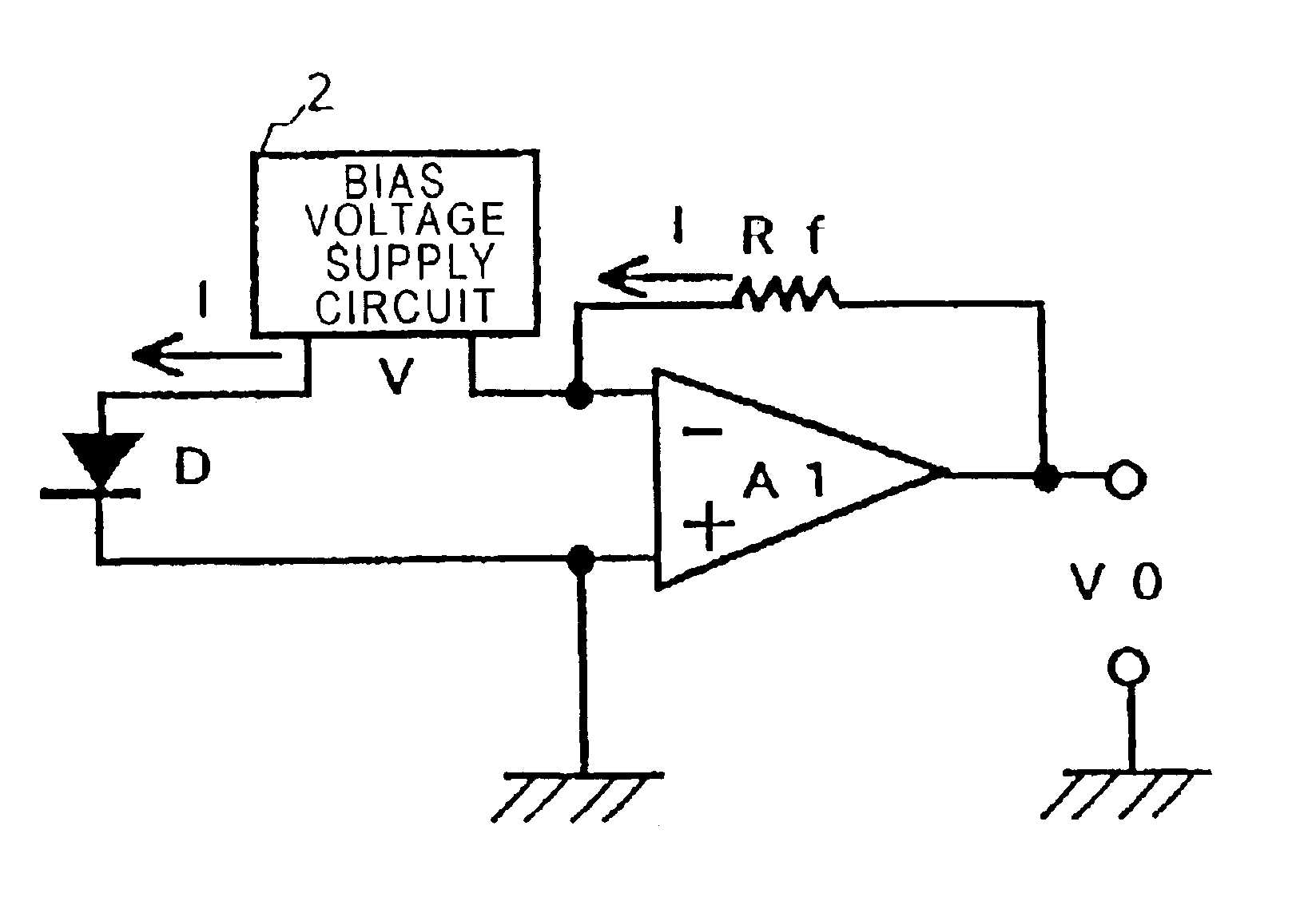
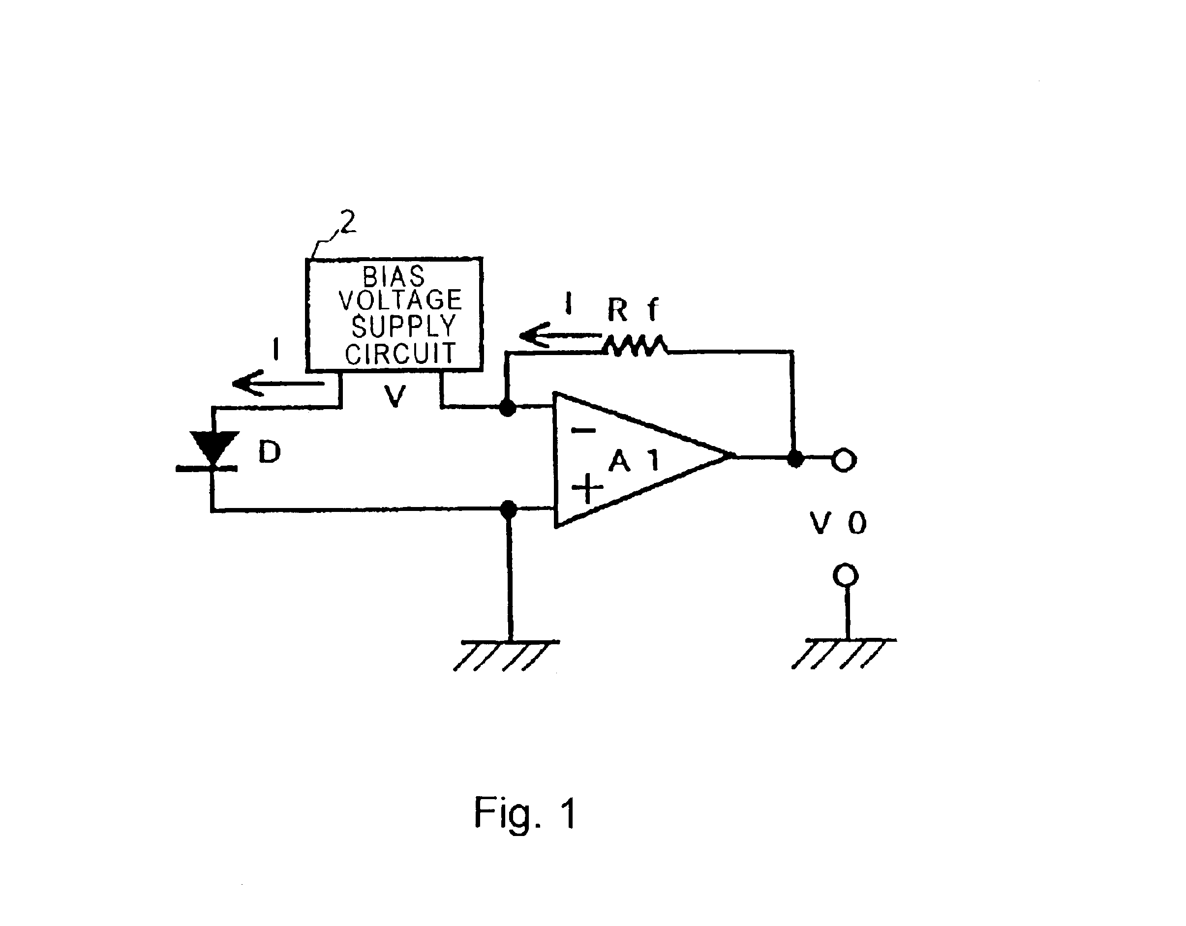
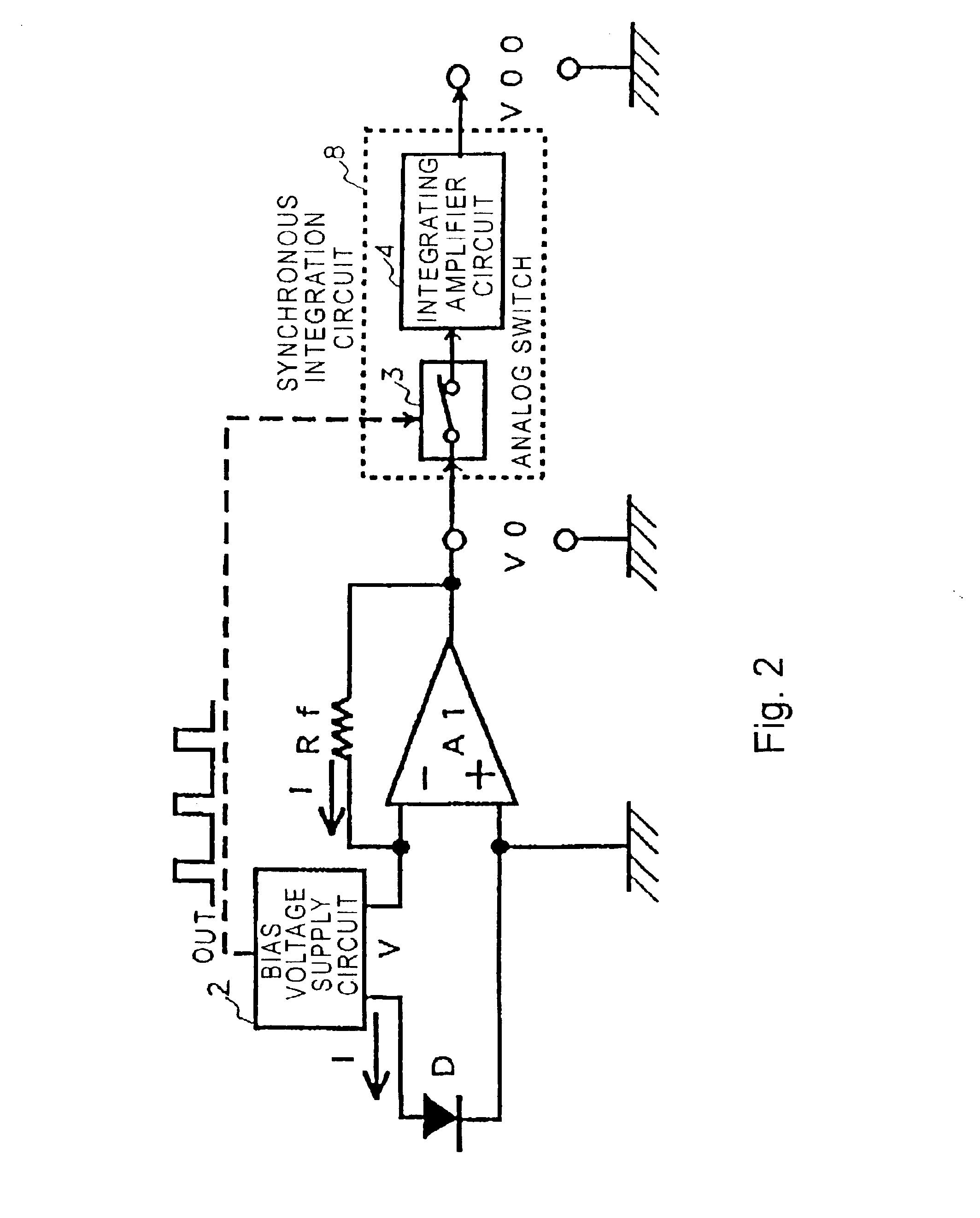
FIG. 2 is a block diagram of a semiconductor diode temperature measurement device according to the invention.

FIG. 2 shows a circuit block diagram in a case where a synchronous integration circuit 8 is added to the configuration of FIG. 1, when a applied forward bias voltage of rectangular or generally-rectangular voltage waveform is further applied thereto as an output voltage from the bias voltage supply circuit 2 instead of a direct current applied forward bias voltage which can be set at a desired voltage. In this synchronous integration circuit 8, for example, a rectangular wave voltage OUT in synchronization with a applied forward bias voltage from the bias voltage supply circuit 2 is applied to an analog SW (switch) 3 as shown by a broken line to switch it, and an output voltage V0 from the operational amplifier A1 goes into the integrating amplifier circuit 4 synchronously, whereby an output voltage V00 with an improved SN ratio can be obtained, as described above. Note that ...


PUM


Abstract

At least one forward-biased semiconductor diode having a potential barrier is used as a temperature sensor whose sensitivity can be finely adjusted. An operational amplifier circuit (A1) is used to apply a bias voltage of DC or rectangular waveform to a semiconductor diode (D) having a potential barrier used as a temperature sensor. In view of the fact that the temperature sensitivity of the semiconductor diode (D) depends on the height of its potential barrier, the forward bias voltage applied from a bias circuit (2) directly to the semiconductor diode (D) is finely adjusted to obtain desired temperature sensitivity. The output voltage of the sensor is associated with a current, having an exponential temperature dependence, which flows in the semiconductor diode (D) with the forward bias being fixed.

Description

FIELD OF THE INVENTIONThe invention relates to a temperature measurement device with a semiconductor diode, a thermal infrared image sensor, and a method of measuring temperature. For example, the invention is used for detecting a temperature distribution in an integrated circuit, and used as a flow sensor, a Pirani gage, a thermal infrared sensor, a thermal infrared thermometer, thermal infrared image sensor, and the like.DESCRIPTION OF THE RELATED ARTA temperature sensor, in which the p-n junction of semiconductors is utilized, has been developed heretofore. This temperature sensor, which utilizes the temperature dependence of forward build-up voltage of a p-n junction diode, namely the fact that a forward bias voltage Vf in flowing a constant current is proportional to the temperature (absolute temperature) T, is referred to as a diode temperature sensor. In addition, a bipolar transistor has a p-n junction between the emitter and base likewise, so that there is a temperature sen...

Claims


Application Information

Patent Timeline
IPC IPC(8): G01J1/44G01J5/20G01J5/22G01K7/01H04N5/33G01J1/42G01J5/48H01L27/14H01L27/146H01L35/00
CPCG01J1/44G01K7/01G01J5/22H04N5/33
Inventor KIMURA, MITSUTERU
Owner JAPAN SCI & TECH CORP
Why Eureka
Try Eureka