

Air conditioning valve actuator for a motor vehicle
a technology for air conditioning valves and motor vehicles, which is applied in vehicle heating/cooling devices, dynamo-electric machines, and element comparison, etc. it can solve the problems of difficult to cope, increase in available mechanical power, torque, and electric power consumption extremely quickly, and achieves less noise when, small size and weight, and high efficiency
Inactive Publication Date: 2005-02-08
SOC IND DE SONCEBOZ
View PDF20 Cites 11 Cited by
- Summary
- Abstract
- Description
- Claims
- Application Information
AI Technical Summary
Benefits of technology
"The present invention provides an air-conditioning valve-actuator for a motor vehicle that generates less noise, has higher efficiency, and is smaller and lighter than existing actuators. The actuator uses an electric motor with a permanent magnet and a reduction unit to increase the output torque. The motor has a high current-supply frequency that allows for a gradual increase in power, reducing the need for a start-stop operation. The actuator includes a controller to control the power of the motor, which maintains a constant voltage and allows for a smooth transition to the high current-supply frequency. The actuator is also designed to have a lower γ2 / R0 factor, which reduces the size and weight of the motor."
Problems solved by technology
Besides the problems of manufacturing costs related to the power used and the size of the motors used, the movements of the shutters, when opening and closing, as well as the motors themselves generate sound problems that can difficultly be coped with through sound-insulating means, since the sound waves are conveyed through the ventilation conduits.
Furthermore, with a coil resistance maintained constant, the available mechanical power, the torque and the electric-power consumption extremely quickly increase with the power-supply voltage.
The voltage of a non-controlled battery however varies between 8 and 14 Volt, so that the motor mostly operates at a voltage higher than 8 Volt, which, because of the increase in available mechanical power, torque and electric-power consumption, besides the increased noise, is also prejudicial to the valve's lifetime, since this causes, on the one hand, at the level of the reduction unit, an excessive blocking torque likely to damage the toothing of the latter and, on the other hand, an overheating of the winding of the motor.
Method used
View moreImage
Smart ImageViewing Examples

Examples
first embodiment
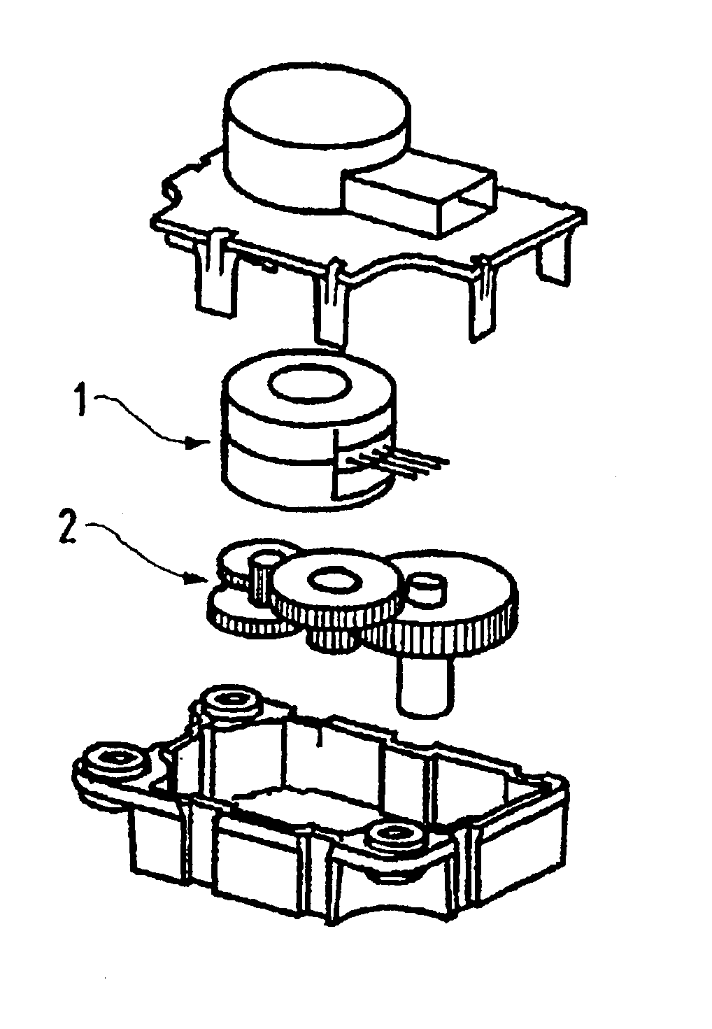
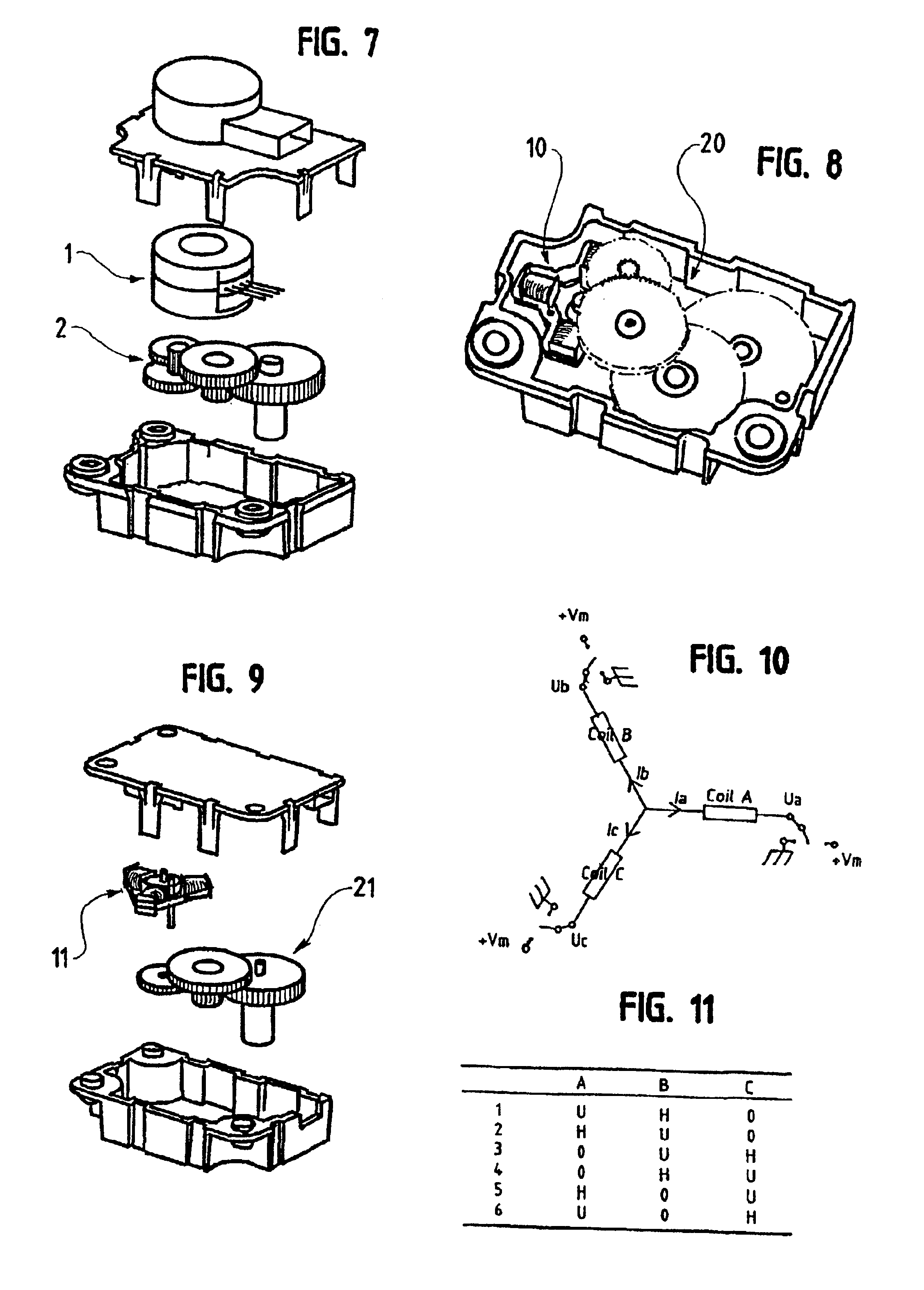
[0047]FIG. 7 is a perspective and exploded view of the motor of the actuator according to the invention.
second embodiment
[0048]FIG. 8 is a perspective view of the motor of the same actuator.
third embodiment
[0049]FIG. 9 is a perspective and exploded view of the motor of the same actuator.
[0050]FIG. 10 shows a diagrammatic illustration of the control mode for the motor described in FIG. 9.
[0051]FIG. 11 is a table showing the various power-supply sequences for the same motor.
Login to View More PUM
 Abstract
An air conditioning valve actuator for a motor vehicle operating on an electric step motor with a permanent magnet capable of delivering mechanical power at least equal to 50 mW, and a reduction unit for decreasing the amplitude of the angular pitch and increase the output torque. The motor is defined by the following relationship: 10−6<γ2 / R0<, wherein: γ is the torque constant, proportional to the magnet volume and, R0 is the characteristic coefficient of the volume of copper and the length of the average turn of the coils, in which R0=ρ.Lsp / (Scu.σ), ρ being the resistivity of copper, Lsp being the length of the average turn of a coil, Scu being the copper section of a coil and σ the filling coefficient of a coil. A controller is cooperative with the motor power supply enabling to accelerate gradually the frequency of the supply of the windings.
Description
RELATED U.S. APPLICATIONS[0002]Not applicable.STATEMENT REGARDING FEDERALLY SPONSORED RESEARCH OR DEVELOPMENT[0003]Not applicable.REFERENCE TO MICROFICHE APPENDIX[0004]Not applicable.FIELD OF THE INVENTION[0005]The present invention relates to an air conditioning valve actuator for a motor vehicle.BACKGROUND OF THE INVENTION[0006]Generally, an air-conditioning installation for a motor vehicle comprises valves including shutters, the opening and closing of which are motor-controlled by means of electric motors, such as stepper motors with permanent magnets, each associated with a reduction unit.[0007]These air-conditioning installations for motor vehicles, which can be of the type as disclosed in DE 4343385 and FR 2731852, have many drawbacks. Besides the problems of manufacturing costs related to the power used and the size of the motors used, the movements of the shutters, when opening and closing, as well as the motors themselves generate sound problems that can difficultly be cop...
Claims
Login to View More Application Information
Patent Timeline
 Patent Type & AuthorityPatents(United States)
IPC IPC(8): H02K37/10H02K37/14H02K37/24B60H1/00
CPCH02K37/10
InventorGANDEL, PIERREPRUDHAM, DANIELDIETZ, DANIEL
OwnerSOC IND DE SONCEBOZ