Radial line slot antenna
a technology of antenna and slot, applied in the field of radial line slot antenna, can solve the problems of insufficient frequency band allocated to various communication equipment, insufficient development of a technology required for shifting to higher frequency band, and enormous amount of time for fine adjustment, etc., to achieve high precision, improve performance, and facilitate the effect of energising the antenna array
- Summary
- Abstract
- Description
- Claims
- Application Information
AI Technical Summary
Benefits of technology
Problems solved by technology
Method used
Image

Examples
first embodiment
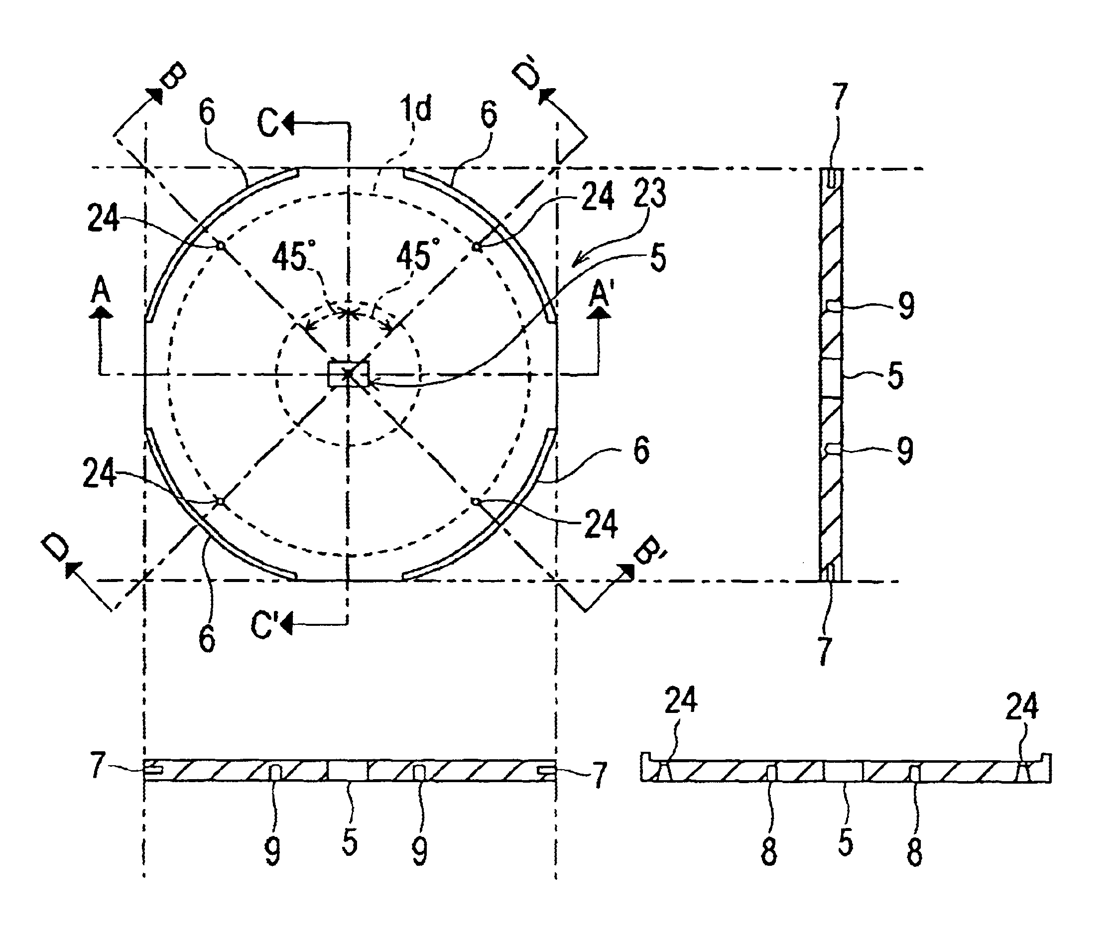
FIG. 6 is a plan view depicting the configuration of the rear side of the antenna disk 21 in the first embodiment of the RLS antenna according to the present invention.
FIG. 7 are diagrams depicting the configuration of the RLS antenna feeder disk according to the first embodiment. FIG. 7a is a plan view depicting the configuration of the front side of the feeder disk, and FIG. 7b is a diagram depicting the configuration of the A-A′ cutting plane of the feeder disk. FIG. 7c is a diagram depicting the configuration of the C-C′ cutting plane of the feeder disk, and FIG. 7d is a diagram depicting the configuration of the B-B′ and D-D′ cutting planes of the feeder disk. And FIG. 7e is a plan view depicting the configuration of the rear side of the feeder disk.
In FIG. 6 and FIG. 7, composing elements identical with or equivalent to the above mentioned prior art described with reference to FIG. 1 to FIG. 4 are denoted with identical reference numerals, for which redundant descriptions are ...
second embodiment
FIG. 8 is a plan view depicting the general configuration of the rear side of the antenna disk in the RLS antenna according to the second embodiment of the present invention.
FIG. 9a-FIG. 9f are diagrams depicting the configuration of the RLS antenna feeder disk according to the second embodiment. FIG. 9a is a plan view depicting the configuration of the front side of the feeder disk, and FIG. 9b is a diagram depicting the configuration of the A-A′ cutting plane of the feeder disk. FIG. 9c is a diagram depicting the configuration of the C-C′ cutting plane of the feeder disk, and FIG. 9d is a diagram depicting the configuration of the D-D′ cutting plane of the feeder disk. FIG. 9e is a diagram depicting the configuration of the B-B′ cutting plane of the feeder disk, and FIG. 9f is a plan view depicting the configuration of the rear side of the feeder disk.
In the second embodiment, composing elements identical with or equivalent to the above mentioned first embodiment described with re...
third embodiment
In the third embodiment, the feeder disk 23 is created by conductivity-added plastic mold, while in the first and second embodiment, the feeder disk 23 is created from brass material, aluminum material or conductive plastic material, which is mechanically processed using a lathe or drilling machine.
For the conductivity-added plastic molding, engineering plastic material (e.g. liquid crystal polymer, polysultone, polyether sulfone, polyphenylene sulfide, polyether ether ketone, polyallylate, polyether imide) is used. To add conductivity, carbon material or conductive paint is coated on the feeder disk 23 created by plastic mold, or a metal coat, such as aluminum, is deposited.
The feeder disk 23 may be created by molding the conductive plastic material (e.g. polyacetylene, polyaniline, polythiophene, polypyrrole, and other polymers) so that processing after the above mentioned “add conductivity” step is unnecessary.
According to the third embodiment, the feeder disk 23 shown in the fir...
PUM
 Abstract
Description
Claims
Application Information
 - R&D
- Intellectual Property
- Life Sciences
- Materials
- Tech Scout
- Unparalleled Data Quality
- Higher Quality Content
- 60% Fewer Hallucinations
Browse by: Latest US Patents, China's latest patents, Technical Efficacy Thesaurus, Application Domain, Technology Topic, Popular Technical Reports.
© 2025 PatSnap. All rights reserved.Legal|Privacy policy|Modern Slavery Act Transparency Statement|Sitemap|About US| Contact US: help@patsnap.com