Electrolytes for electrooptic devices comprising ionic liquids
a technology of electrooptic devices and electrooptic devices, applied in the direction of non-aqueous electrolyte cells, photosensitive materials, instruments, etc., can solve the problems of limited commercial window applications of these ec devices, high cost and lack of durability, and the durability limitation of ec devices
- Summary
- Abstract
- Description
- Claims
- Application Information
AI Technical Summary
Benefits of technology
Problems solved by technology
Method used
Image
Examples
example 1
Absorbance spectrum of UV stabilizer in ionic liquid solvent. The absorbance spectra propylene carbonate, 1-Butyl-3-methylimidazolium bis(trifluoromethylsulfonyl)imide (BMI), N-butyl-N-methylpyrrolidinium bis(trifluoromethylsulfonyl)imide (BMP), and a solution of BMI with 1% commercial UV stabilizer called Uvinul 3035 (ethyl 2-cyano-3,3-diphenyl-acrylate, available from BASF, Mount Olive, N.J.) were measured between 800 and 250 nm. Both BMI and BMP are ionic liquid solvents used with the invention. BMI has higher absorbance in the UV (below 400 nm) than BMP, due to its more conjugated nature. The solution of BMI with 1% UV stabilizer was a clear liquid that did not form a precipitate at −30° C. after 15 hours. The absorbance spectra of the four solutions are shown in FIG. 6.
example 2
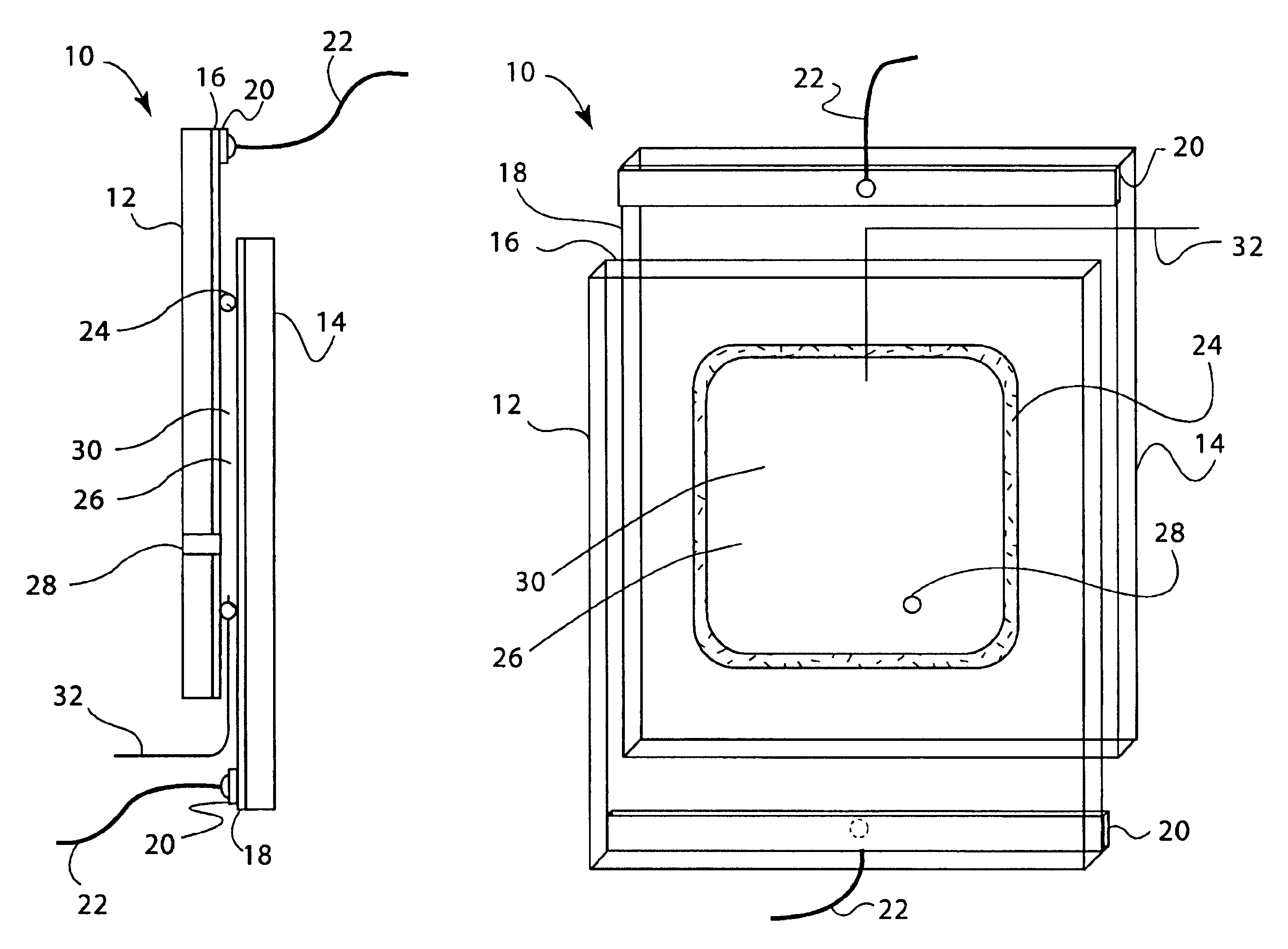
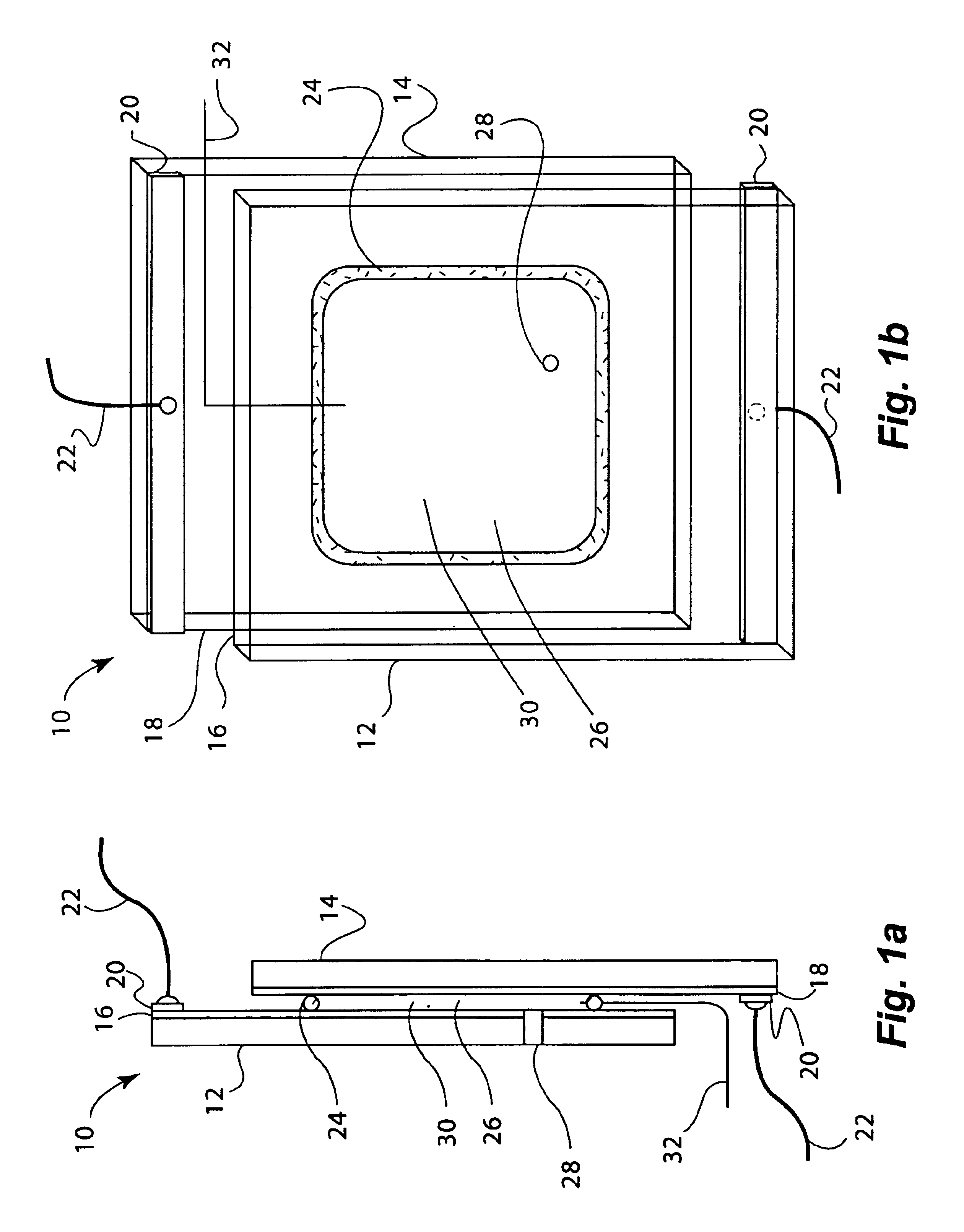
Electrochromic window device with electrolyte solution including redox dye. ITO substrate (15 Ω / sq) was cut into two 5.25″×3.7″ rectangular pieces. Two holes about 3 mm in diameter were drilled into one piece near the corners of one of the diagonals. The substrates were then washed, dried and stored under clean room conditions. An epoxy containing 105 micron glass bead spacers was dispensed around the edges of one of the substrates, and the second substrate was placed on top of it to make a cavity such that the two substrates were slightly off-centered along the long side of the rectangular edge. This exposed edge on both substrates was later used to apply a busbar and make electrical connections. The epoxy seal was cured at a temperature of 120° C. The cavity was filled at room temperature with a liquid electrolyte solution containing 0.015M of the charge transfer complex formed by N,N′-dimethylviologen bis(trifluoromethanesulfonyl)imide (methyl viologen imide salt), 0.015M N,N,N′,...
example 3
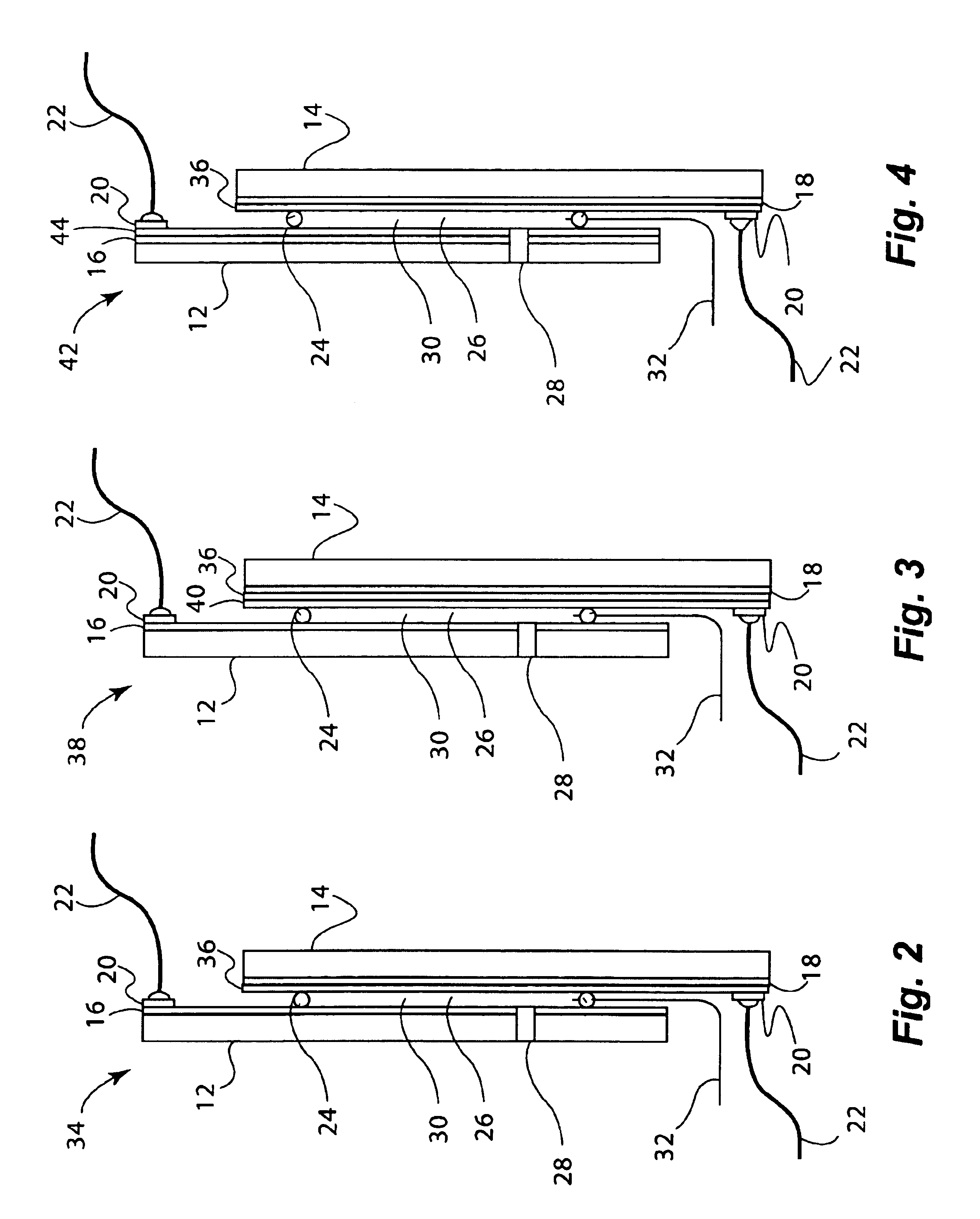
Electrochromic window device having a tungsten oxide coating. Two half wave ITO substrates (15 Ω / sq) were prepared as described in EXAMPLE 2 except that the substrate that was not drilled into was coated with a 300 nm thick tungsten oxide coating (on the conductive side) containing 30 mole % of lithium oxide (based on tungsten atoms). This coating was applied by a wet chemical method as described in U.S. Pat. No. 6,266,177. Any other method such as chemical vapor deposition and physical vapor deposition could have been used to deposit the tungsten oxide layer. The coating was fired at a temperature of 135° C. in a humid atmosphere, and then at 250° C. in air. It was then fabricated into a cell as described in EXAMPLE 1. The cavity thickness was 175 microns. The cavity was filled with electrolyte containing 0.1 molar lithium bis(trifluoromethanesulfonyl)imide, 0.015M ferrocene, 1 weight % Uvinul 3035 (from BASF, Mount Olive, N.J.) dissolved in 1-butyl-3-methylimidazolium bis (trifluo...
PUM
| Property | Measurement | Unit |
|---|---|---|
| Temperature | aaaaa | aaaaa |
| Glass transition temperature | aaaaa | aaaaa |
| Fraction | aaaaa | aaaaa |
Abstract
Description
Claims
Application Information
 - R&D
- Intellectual Property
- Life Sciences
- Materials
- Tech Scout
- Unparalleled Data Quality
- Higher Quality Content
- 60% Fewer Hallucinations
Browse by: Latest US Patents, China's latest patents, Technical Efficacy Thesaurus, Application Domain, Technology Topic, Popular Technical Reports.
© 2025 PatSnap. All rights reserved.Legal|Privacy policy|Modern Slavery Act Transparency Statement|Sitemap|About US| Contact US: help@patsnap.com


