Static NVRAM with ultra thin tunnel oxides

a tunnel oxide and static nvram technology, applied in the field of static nvram with ultra thin tunnel oxides, can solve the problems of falling short, becoming a very complex structure, increasing complexity and difficulty with each generation, etc., and achieves the effect of large gain and relatively fast sense operation

Inactive Publication Date: 2005-03-08
MICRON TECH INC
View PDF78 Cites 38 Cited by
  • Summary
  • Abstract
  • Description
  • Claims
  • Application Information

AI Technical Summary

Benefits of technology

The structures and methods described in the present invention include a “static,” non volatile, “depletion mode” p-channel floating gate transistor, or p-channel flash memory cell having an ultra thin tunnel oxide. The memory cell of the present invention, based on tunneling phenomena and ultra thin gate oxides, is best described as a NVRAM, a non volatile random access memory. It operates on a static or DC basis and has stable DC output currents which can be sensed by current sense amplifiers and / or integrated over some period of time on a capacitor and sensed by differential voltage sense amplifiers. The sense operation can be relatively fast, in the nanosecond time frame, and as such could serve as a DRAM replacement. Thus, there is no longer a requirement for large stacked storage capacitors or deep trench storage capacitors. The large capacitors are unnecessary since the cell now is active in nature and the transistor provides a large gain.

Problems solved by technology

Over the course of time what was a very simple device (a planer capacitor and one transistor) has, because of ever shrinking dimensions, become a very complex structure, to build.
Whether it is the trench capacitor, favored by IBM, or the stacked capacitor, used by much of the rest of the industry, the complexity and difficulty has increased with each generation.
Many different proposals have been proposed to supplant this device, but each has fallen short because of either the speed of the write or erase cycle being prohibitively long or the voltage required to accomplish the process too high.
One of the limitations to shrinking a flash EEPROM memory cell has been the requirement for a silicon dioxide gate insulator thickness of approximately 10 nm between the floating polysilicon gate and the silicon substrate forming the channel of a flash field effect transistor.
This combination of barrier height and oxide thickness results in extremely long retention times even at 250 degrees Celsius.
The simple idea would be that retention times are determined by thermal emission over a 3.2 electron volt (eV) energy barrier, however, these would be extremely long so the current model is that retention is limited by F-N tunneling off of the charged gate.
This combination of barrier height and oxide thickness tunnel oxide thickness is not an optimum value in terms of transfer of electrons back and forth between the substrate and floating gate and results in long erase times in flash memories, typically of the order of milliseconds.
Negatively, higher gate current in the PMOS transistors resulting from this BTB tunneling effect limits the performance of deep sub-micron CMOS technology, as reported by R. Ghodsi et al.

Method used


Image

  • Static NVRAM with ultra thin tunnel oxides
  • Static NVRAM with ultra thin tunnel oxides
  • Static NVRAM with ultra thin tunnel oxides

Examples


Embodiment Construction

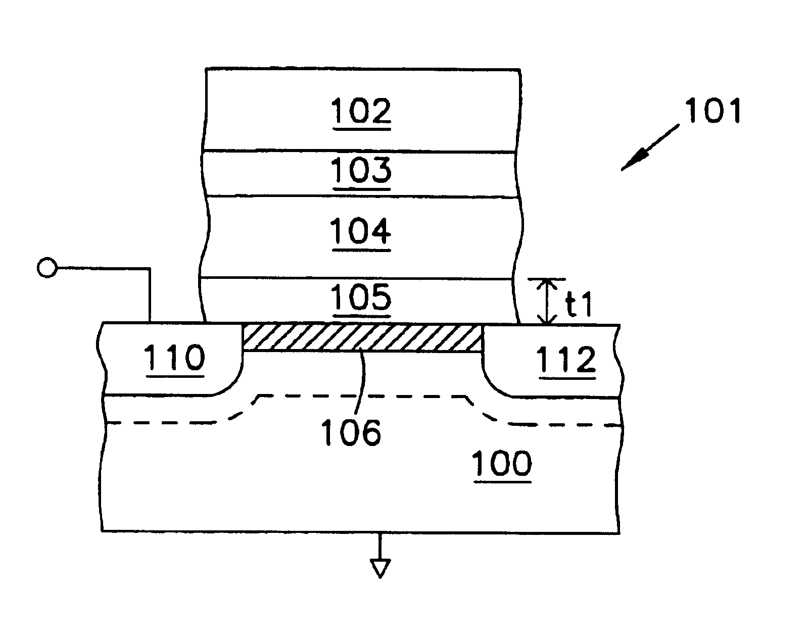
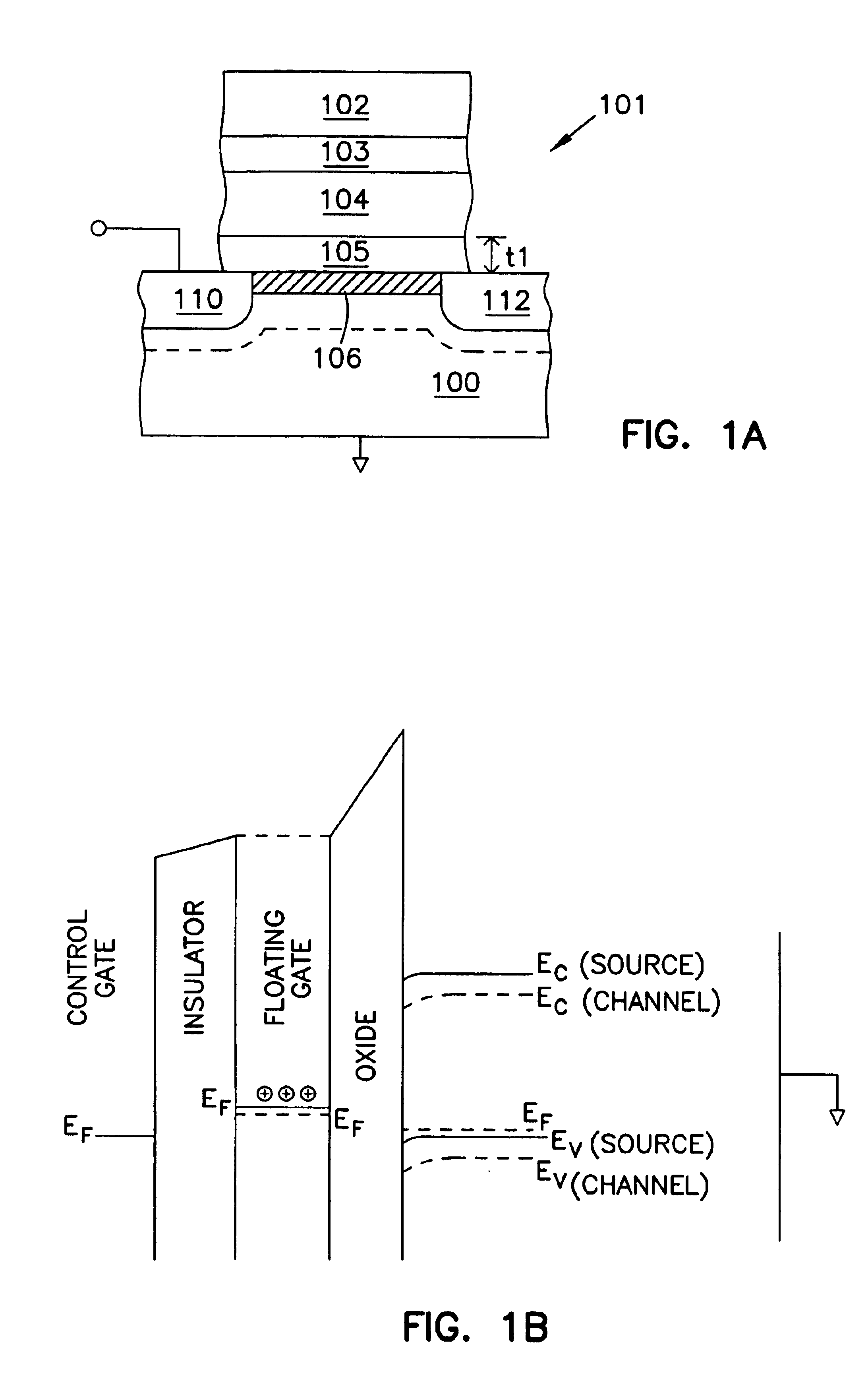
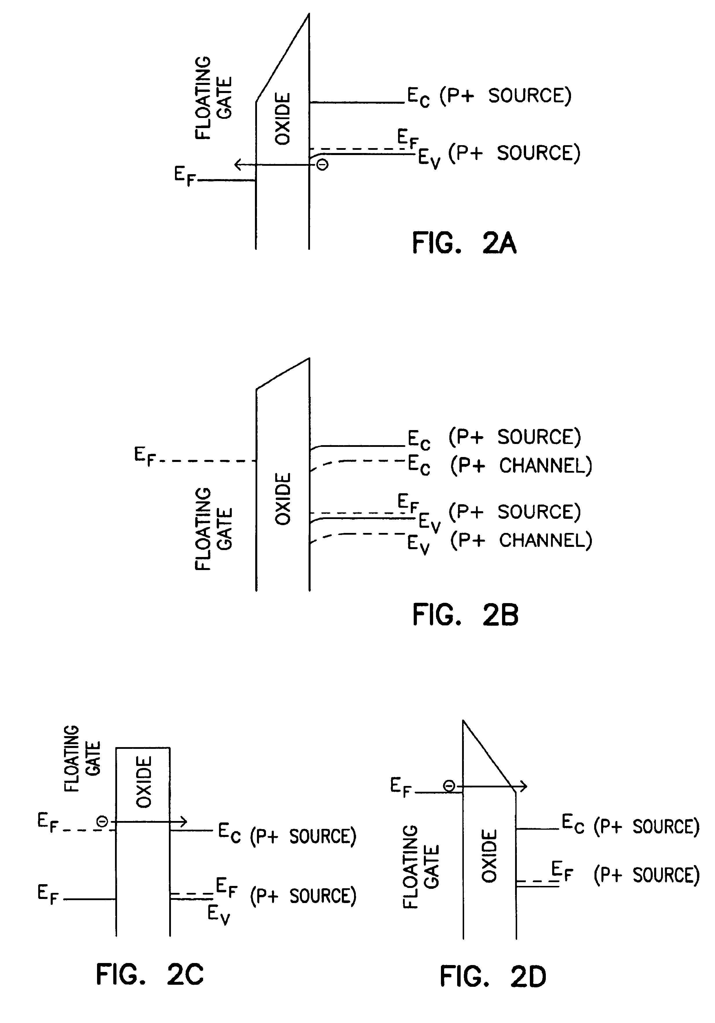
In the following detailed description of the invention, reference is made to the accompanying drawings which form a part hereof, and in which is shown, by way of illustration, specific embodiments in which the invention may be practiced. In the drawings, like numerals describe substantially similar components throughout the several views. These embodiments are described in sufficient detail to enable those skilled in the art to practice the invention. Other embodiments may be utilized and structural, logical, and electrical changes may be made without departing from the scope of the present invention. The terms wafer and substrate used in the following description include any structure having an exposed surface with which to form the integrated circuit (IC) structure of the invention. The term substrate is understood to include semiconductor wafers. The terms wafer and substrate used in the following description include any base semiconductor structure. Both are to be understood as ...


PUM


Abstract

Structures and methods involving non volatile depletion mode p-channel memory cells with an ultrathin tunnel oxide thicknesses, e.g. less than 50 Angstrom (Å), have been provided. Write and erase operations are performed by tunneling. The floating gate of the depletion mode p-channel memory cell is adapted to hold a fixed charge over a limited range of floating gate potentials or electron energies. There is a range potentials applied to the floating gate for which there are no final nor initial states in the silicon substrate or p+ source region. In this range of potentials there can be no charge leakage from the floating gate by tunneling or thermally assisted tunneling. The charge state of the floating gate will modulate the conductivity of the underlying transistor channel, with different stable and non-volatile charge states resulting in different conductivity states. Other aspects are also included.

Description

FIELD OF THE INVENTIONThe present invention relates generally to semiconductor integrated circuits and, more particularly, to structures and methods for static NVRAM with ultra thin tunnel oxides.BACKGROUND OF THE INVENTIONThe use of the one device cell, invented by Dennard in 1967 (see generally, U.S. Pat. No. 3,387,286, issued to R. H. Dennard on Jun. 4, 1968, entitled “Field Effect Transistor memory”), revolutionized the computer industry, by significantly reducing the complexity of semiconductor memory. This enabled the cost, of what was then a scarce commodity, to be drastically reduced.Today, dynamic random access memories (DRAMs) are a mainstay in the semiconductor industry. DRAMs are data storage devices that store data as charge on a storage capacitor. A DRAM typically includes an array of memory cells. Each memory cell includes a storage capacitor and an access transistor for transferring charge to and from the storage capacitor. Each memory cell is addressed by a word lin...

Claims


Application Information

Patent Timeline
Patent Type & Authority Patents(United States)
IPC IPC(8): G11C16/04H01L29/423H01L29/66H01L29/40H01L29/788
CPCG11C16/0416H01L29/7883H01L29/42324
Inventor FORBES, LEONARD
Owner MICRON TECH INC
Why Eureka
Try Eureka