Eureka AIR delivers breakthrough ideas for toughest innovation challenges, trusted by R&D personnel around the world.

Solid electrolytic capacitor

Active Publication Date: 2005-03-08
TOKIN CORP
View PDF6 Cites 8 Cited by
  • Summary
  • Abstract
  • Description
  • Claims
  • Application Information

AI Technical Summary

Benefits of technology

In consideration of the foregoing, it is an object of the present invention to form a dense film by metal plating in order that a conductive polymer, employed in the cathode of the solid electrolytic capacitor element, is not oxidized, thereby improving the reliability of the capacitor.
It is another object of the present invention to form a plating of a metal such as gold or silver which is higher in the melting temperature and chemically more stable than solder, on a surface of an external cathode terminal connected with the cathode of the solid electrolytic capacitor, thereby suppressing a change in an interfacial resistance at the mount of the cathode of the capacitor with the external cathode terminal, and thus improving the reliability of the capacitor.

Problems solved by technology

The conductive polymer employed in the prior solid electrolytic capacitor is associated with a drawback, though initially having a high conductivity, of losing the conductivity by being oxidized in an oxygen-containing atmosphere of a high temperature.
Therefore, in case the interception of oxygen is insufficient in the cathode, ESR will be deteriorated when the solid electrolytic capacitor is exposed to a high temperature over a long period.
The graphite layer and the silver paste layer cannot be formed densely and is therefore unable to sufficiently prevent intrusion of oxygen.
Such plating certainly facilitates soldering, but is associated with a drawback of being partially fused in a surface adhered to the cathode of the capacitor element, thereby causing a peeling of the external cathode terminal and the conductive adhesive and increasing a contact resistance with the cathode electrode.

Method used


Image

  • Solid electrolytic capacitor
  • Solid electrolytic capacitor
  • Solid electrolytic capacitor

Examples


Embodiment Construction

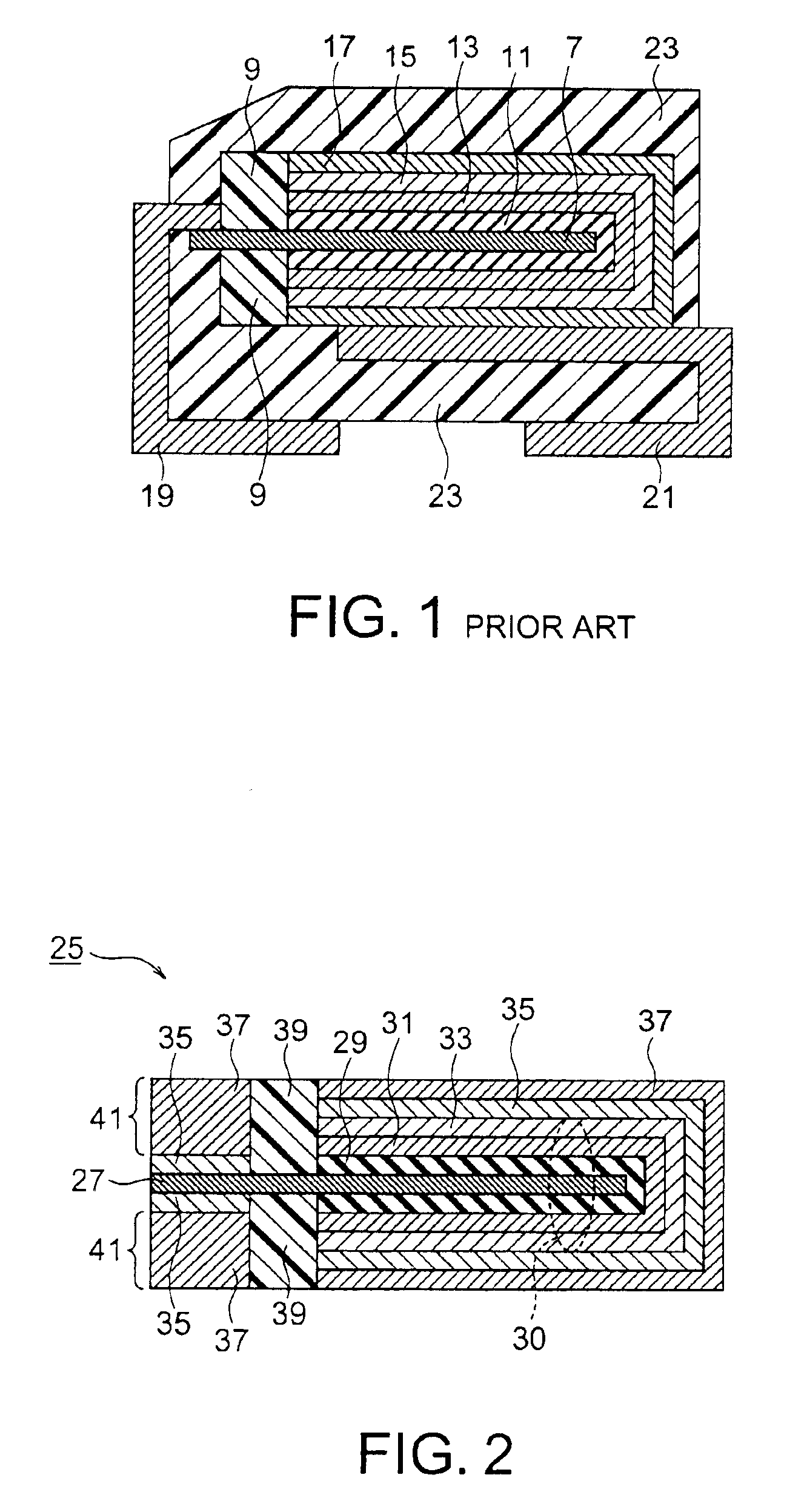
For facilitating the understanding of the present invention, explanation will at first be made of a solid electrolytic capacitor of a related art, with reference to FIG. 1. In the following description, for the convenience of explanation, components of the capacitor may be represented by names or symbols which are different from those in the aforementioned patent references.

Referring to FIG. 1, an aluminum foil 7, subjected to a surface enlargement by etching, which foil will be referred to as an etched aluminum foil, is divided by an epoxy resin member 9, from the left-hand side of the drawing, into an area for connecting an external anode terminal, and a second area for developing a capacity. In the capacity developing area, constituting a major portion of the aluminum foil 7 at the right-hand side of the drawing, there is formed an aluminum oxide film 11 obtained by anodizing the aluminum foil 7 constituting a base member.

On and in intimate contact with the aluminum oxide film 11...


PUM


Abstract

The invention provides a solid electrolytic capacitor of a configuration having a metal plated layer in a cathode part in order to prevent a decrease in the conductivity by oxidation of a conductive polymer and to realize a high reliability. Also there is provided a configuration in which a cathode part of the solid electrolytic capacitor includes a first metal plated layer and a solderable second metal layer.

Description

The present application claims priority to prior Japanese application JP 2002-248011, the disclosure of which is incorporated herein by reference.BACKGROUND OF THE INVENTIONThe present invention relates to a solid electrolytic capacitor, and more particularly to a solid electrolytic capacitor utilizing a conductive polymer as a solid electrolyte.A solid electrolytic capacitor has a configuration constituted by forming an anode with a valve-action metal such as tantalum, niobium or aluminum, oxidizing a surface of the anode to form a dielectric member, forming thereon a closely contacting layer of manganese dioxide or a conductive polymer, and forming on that layer a graphite layer or a silver paste layer as a cathode.The manganese dioxide or the conductive polymer constitutes a solid electrolyte, and particularly the conductive polymer is being employed frequently in recent years, as it has a high conductivity and can reduce an equivalent series resistance (ESR) of a capacitor.The s...

Claims


Application Information

Patent Timeline
IPC IPC(8): H01G9/00H01G9/04H01G9/008H01G9/012H01G9/08H01G9/15H01G9/048H01G9/042H01G9/045
CPCH01G9/012H01G9/04H01G9/028H01G9/0425H01G9/045H01G9/042H01G9/048
Inventor ARAI, SATOSHIINOI, TAKAYUKISAIKI, YOSHIHIKOTOITA, SADAMU
Owner TOKIN CORP
Why Eureka
Eureka Blog
Learn More