
System and method for frequency management in a communications positioning device

Inactive Publication Date: 2005-03-15
GOOGLE TECH HLDG LLC
View PDF15 Cites 181 Cited by
  • Summary
  • Abstract
  • Description
  • Claims
  • Application Information

AI Technical Summary

Benefits of technology

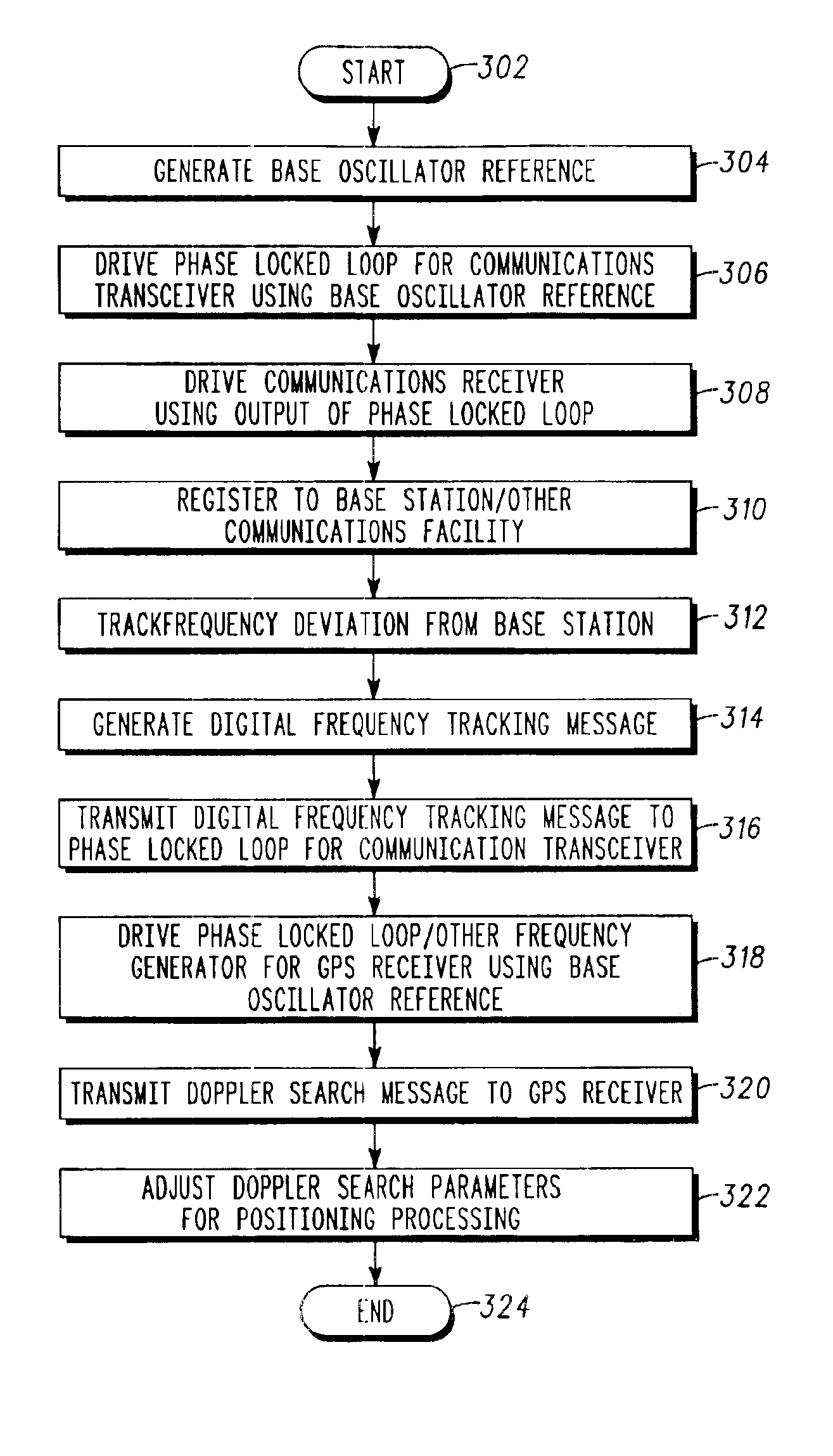
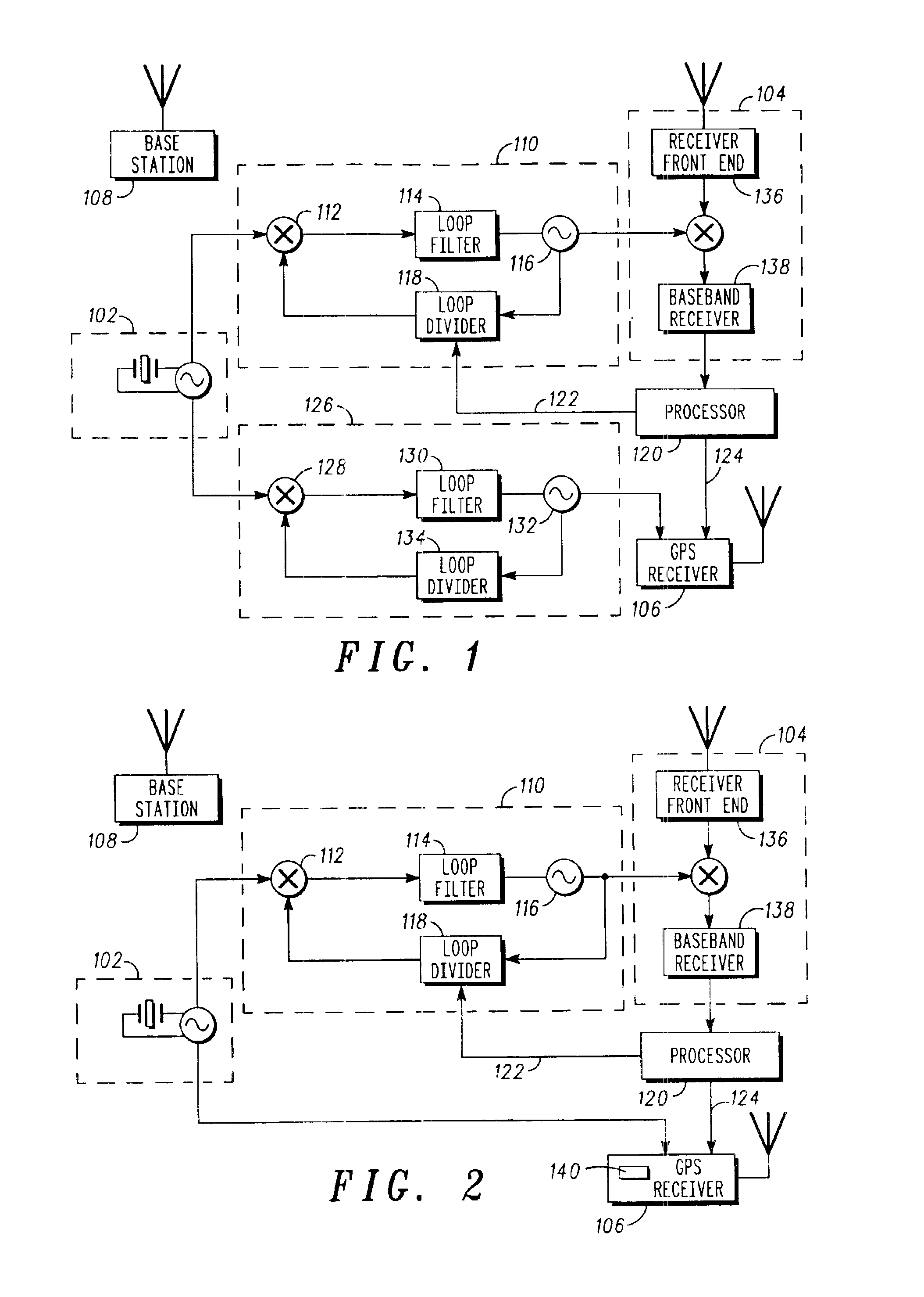
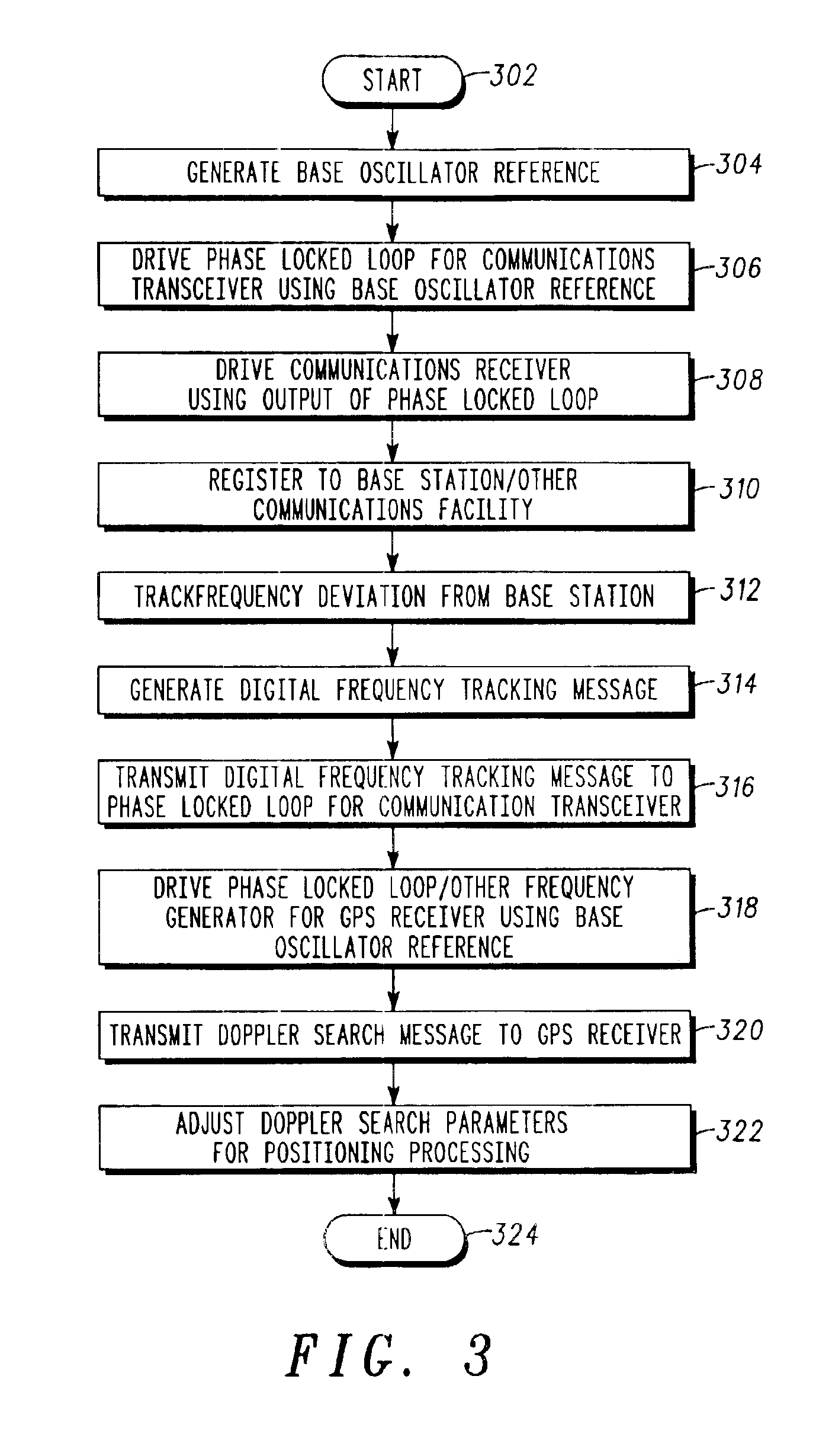
The invention overcoming these and other problems in the art relates in one regard to a system and method for frequency management in a combined communications / positioning system, in which a stable base reference may be derived for GPS purposes from a baseline frequency reference used to drive the communications side of the device. That baseline reference may in embodiments operate without direct correction such as for instance software temperature correction, hardware temperature correction, measurement of frequency bias at time of manufacture, automatic frequency control (AFC) or other techniques to establish accuracy in the communications portion of the device. The GPS receiver component may consequently receive that baseline reference and upconvert that reference to GPS frequencies, using an intermediate oscillator, integrated synthesizer or other element. The frequency reference for the positioning portion of the device will consequently also exhibit the same range of frequency variance as the original communications (baseline) clock. However, according to embodiments of the invention, a processor element communicating with the communications portion of the device may track frequency drift based on deviation from cellular base or other factors. That processor or other logical element may consequently communicate a Doppler search or other logical digital message to the positioning portion of the device, indicating the deviation of the original communications frequency reference. This logical digital message may contain predictive frequency information such as frequency drift rate which may be derived from thermodynamic properties of the system, along with empirical data and associated algorithms. The positioning receiver may then adjust the center frequency or width of the Doppler search window, frequency scan rate, or other search parameters to drive the position acquisition and tracking processing to be faster, sensitive to lower signal strengths, and have better position accuracy. The GPS or other positioning portion of the combined device therefore need not contain a local oscillator of its own, while still achieving sufficient GPS performance at comparatively low cost.

Problems solved by technology

However, the accuracy of reference clocks generally employed in cellular telephones and other communications devices may generally not be as great as that needed for useful GPS service, which as noted may require accuracy to within at least a few parts per million, down to tenths of 1 part per million or less for increased performance in acquisition time, tracking, sensitivity, position accuracy and other factors.
A cellular handset's internal clock may therefore not be sufficient to drive GPS circuitry in a combined device for useful GPS operation by itself.
Temperature compensation circuits operating on ordinary crystal oscillators may improve the frequency reference to perhaps ±5 ppm or so, although those types of parts may add to the cost of a relatively low-cost mobile device.
Solutions such as supplying two corrected reference oscillators, one for GPS and one for cellular or other communications service at different frequencies, for instance, may not be economical in a combined device.
Other problems exist.

Method used


Image

  • System and method for frequency management in a communications positioning device
  • System and method for frequency management in a communications positioning device
  • System and method for frequency management in a communications positioning device

Examples


Embodiment Construction

An architecture in which a frequency management system according to the invention may be implemented is illustrated in FIG. 1, in which a combined communications / positioning device incorporates both GPS receiver circuitry 106 and a communications transceiver 104. As illustrated, the communications transceiver 104 may include a receiver front end 136 for detection and downconversion of communications carrier signals, such as cellular telephone or other radio frequency (RF) or other signals, as well as a baseband receiver 138 for processing downconverted communications signals. The communications transceiver 104 of the combined device may be or include for instance a portable radio, cellular telephone, two-way or other pager, wireless modem, wireless personal digital assistant or other device that receives or transmits a radio, optical or other wireless communications signal. In embodiments, the communications transceiver 104 may communicate with or receive signals from a base station...


PUM


Abstract

A frequency management scheme for a hybrid communications / positioning device, such as a cellular / GPS or other combined device, generates a local clock signal for the communications portion of the device, using a crystal oscillator or other part. The oscillator output may be delivered to a phase locked loop to drive a high-frequency clock for the cellular or other communications portion of the hybrid device. A processor may determine frequency error between the phase locked loop and base station or other reference, to derive a digital frequency tracking message. A Doppler search or other logical control message may likewise be communicated from the processor to a GPS or other positioning receiver. The GPS receiver circuitry may consequently adjust Doppler center, window width or other parameters to enhance time to first fix or other performance. The architecture eliminates the need for a second crystal or other direct oscillator in the GPS receiver portion of the hybrid device, while still maintaining GPS performance. The architecture of the design also eliminates the need for frequency correcting elements in the crystal oscillator or other base reference oscillator or clock. The invention can furthermore be used in any system, radio, modem, transceiver, or receiver that has two or more receivers that share one reference or base oscillator or clock.

Description

FIELD OF THE INVENTIONThe invention relates to the field of communications, and more particularly to techniques for generating and managing precision frequency sources in cellular telephones or other communications devices having a positioning capability, such as Global Positioning System (GPS) or other location service.BACKGROUND OF THE INVENTIONGPS receivers can be characterized by performance criteria such as acquisition and tracking time, which reflect the amount of processing necessary to detect and lock on to GPS satellite signals and hence the amount of time needed to begin accurately reporting a user's position. The acquisition time, tracking ability, sensitivity, position accuracy and other performance parameters of GPS receivers can be affected by a variety of factors. Those factors include the precision with which frequency references for radio frequency detection and other purposes can be generated and managed within the device. L1 GPS signals used for civilian coarse ac...

Claims


Application Information

Patent Timeline
IPC IPC(8): G01S1/00H03J7/02H03J7/06G01S19/12G01S19/23G01S19/25G01S19/35G01S19/48H04B1/16H04B1/38H04B1/40
CPCG01S19/235H03J7/065H04B1/403H03L7/23H04B1/3805H03L7/183H03J2200/11H04W56/00H04W64/00H04B7/185G01S5/0221
Inventor VOOR, THOMAS E.TAWADROUS, SAMEH W.DECK, RONALD H.
Owner GOOGLE TECH HLDG LLC
Learn More