Volume holograms in transparent materials

a technology of transparent materials and holograms, applied in the field of production of volume holograms in transparent materials, can solve the problems of limited use of holograms, requires the use of complex optical setups, and does not save field phase distribution

Inactive Publication Date: 2005-03-29
UCLT
View PDF16 Cites 27 Cited by
  • Summary
  • Abstract
  • Description
  • Claims
  • Application Information

AI Technical Summary

Benefits of technology

Without getting involved in the mathematical details of diffraction theory, the process can be visualized by analogy with the well-known effect of the polychrornatic iridescent appearance of compact discs (CD's) when viewed in white light. Data records on the surface of CD's are formed by a series of pits having a low reflection coefficient. These pits are produced directly by laser thermoplastic etching, or by a polycarbonate injection molding process using a master copy previously created by laser etching. Usually there is no correlation of pit position along the track The polychromatic iridescent appearance of the CD is due to the diffraction of illuminating light from the coherent arrangement of pit tracks next to each other. A mathematical evaluation shows that in order to obtain this effect, there need to be several hundred pits in one coherence length of the illuminating light. The size of typical CD pits varies from 0.75 μto 1.5 μ, and the distance between them varies from 1 μ along the track length to 2.5,μ between adjacent tracks. The coherent length of sunlight is typically of the order of 1 mm. Hence, the pit density of a typical CD is twice as high as that required to produce the characteristic polychromati

Problems solved by technology

This method provides a copy of the field intensity distribution in the lens focal plane, but does not save the field phase distribution.
The problem with the prior art conventional method of producing holograms on photographic recording materials, is that it requires the use of a complex optical set-up, with coherent writing and reading beams for respectively producing and displaying the holograms.
Furthermore, such holograph production methods require either the presence of the object sample itself or involve a complicated method of wav

Method used


Image

  • Volume holograms in transparent materials
  • Volume holograms in transparent materials
  • Volume holograms in transparent materials

Examples


Embodiment Construction

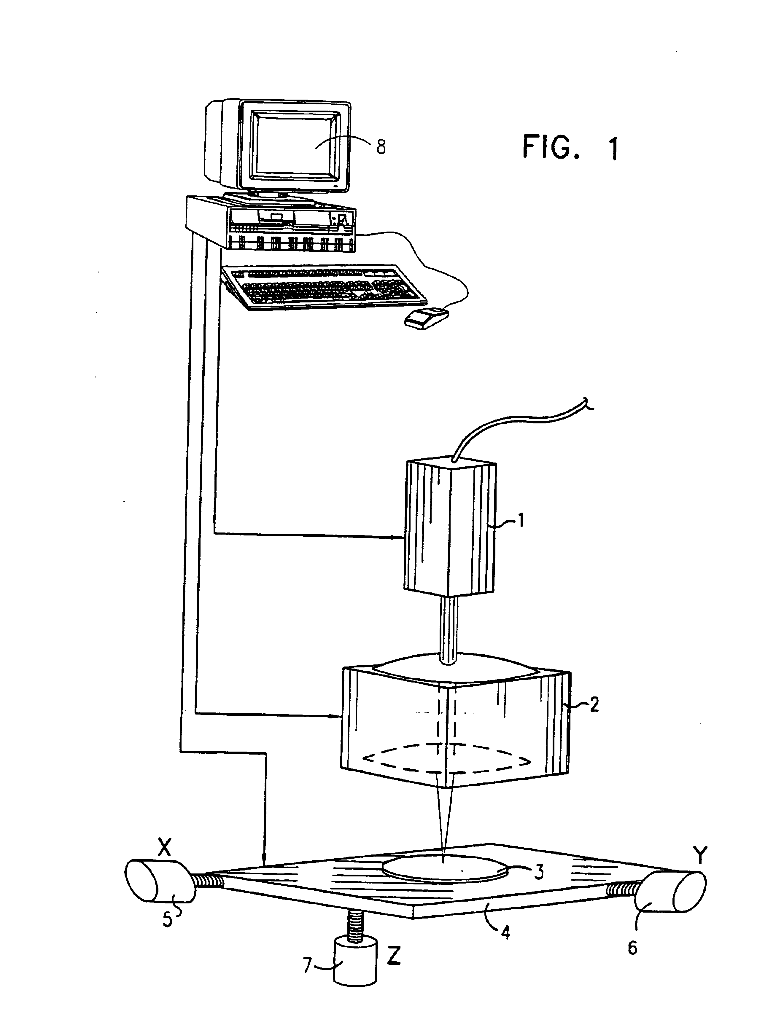
Reference is now made to FIG. 1, which illustrates schematically a computer controlled system for the production of computer generated volume holograms, constructed and operative according to a preferred embodiment of the present invention. A picosecond pulsed laser 1 emits a beam which is preferentially focused by means of a high quality optical system 2, into a transparent sample 3 in which the CGVH is to be produced. The laser pulse peak power, and the diffraction limit of the optical focusing system are such to ensure that the optical breakdown limit for the particular material of the sample is exceeded.

The sample is disposed on a CNC-controlled three-axis precision stage 4. The motions along the X-Y-Z axes is executed by means of CNC motors 5, 6, 7. A computer 8 is operative to control all of the functions of the system, synchronizing the firing of the laser pulses with the motion of the X-Y-Z axes, such that the required volume pattern of scattering points is formed in accorda...


PUM


Abstract

This invention discloses a method of producing, in a solid transparent material (3), a hologram of an object; the method includes the steps of: developing a three-dimensional mathematical model of an electro-magnetic field emanating from the object, the field producing an image of the object; computing a corresponding three-dimensional set of points, light scattered from which reconstructs the field; and focusing a pulsed laser beam into the solid transparent material onto each of the points sequentially, the beam being capable, when focused, of causing optical breakdown in the solid transparent material.

Description

FIELD OF THE INVENTIONThe present invention relates to the field of the production of volume holograms in transparent materials, especially by means of digital laser engraving at very high energy densities.BACKGROUND OF THE INVENTIONAn object can be seen if it reflects, scatters or radiates light. This light can be described by a set of waves of an electromagnetic field. If the same electromagnetic field, called hereinafter in this specification, the model field, were to be recreated by other means, an observer would see the same image. The simplest way of creating a copy of a model field is by means of a photograph. This method provides a copy of the field intensity distribution in the lens focal plane, but does not save the field phase distribution. Phase distribution contains information about location in object space. That is why a true image can be seen only from one viewpoint.A method of preserving this phase information in the copy of the model field is by means of a hologram...

Claims


Application Information

Patent Timeline
IPC IPC(8): G03H1/08
CPCG03H1/08G03H2001/0478Y10S359/90G03H2260/62G03H2001/0484
Inventor GULETSKY, NIKOLAY NIKOLAEVICHDMITRIEV, VLADIMIR YUREVICHOSHEMKOV, SERGEY VIKTOROVICH
Owner UCLT
Why Eureka
Try Eureka