
Liposuction cannula device and method

a cannula and liposuction technology, applied in the field of liposuction apparatus and method, can solve the problems of reducing the reproducibility of the result between the patient's right and left sides, less than optimal, and excessive time for liposuction, and achieve the effect of reducing the total energy

Inactive Publication Date: 2005-04-05
LAWRENCE LIVERMORE NAT SECURITY LLC
View PDF8 Cites 22 Cited by
  • Summary
  • Abstract
  • Description
  • Claims
  • Application Information

AI Technical Summary

Benefits of technology

Another object of the invention is to provide a liposuction apparatus and method which utilizes a combination of reciprocating energy (rectilinear or axial) and ultrasonic energy in which the dual use reduces the total energy of each type necessary to complete a “given” liposuction surgery.

Problems solved by technology

Unfortunately, chronic and acute stress on the surgeon's elbow and shoulder can fatigue the surgeon, thus reducing the reproducibility of the result between the patient's right and left sides, and sometimes making for a less than optimal result.
Unfortunately, liposuction would take excessive time to perform with ultra-small (less than 2 mm) cannulas.
This work takes numerous hours to perform and is impractical for the average surgeon with typical time and anesthetic constraints.
Unfortunately, these larger diameter cannulas often leave noticeably large waves behind in the patient's target fat area and surface skin resulting in an unpleasant, non-uniform appearance to the skin.
Larger diameter cannulas remove fat faster, but require greater effort and tissue trauma.
It is difficult to find a happy medium, although sometimes the choice of a cannula tip can reduce the exertion necessary to pass through fibrous fat.
Fat stored in the body may be encapsulated in cells and is not truly solid to any degree.
Parisi saw early on that the tremendous heat generated by the ultrasonic liposuction cannula could be detrimental to the patient and therefore requires significant cooling measures.
The material which follows will demonstrate three generations of ultrasonic liposuction cannulas based upon the Parisi patents, which still do not provide an adequate solution.
Disadvantageously, the metal cooling sleeve leaves only a fraction of an inch of vibrating shaft (tip) exposed to the patient's tissue.
A major drawback for the third generation of ultrasonic cannulas is that there is incomplete suction of the sonicated (broken and foamy) fat out of the patient's tissues.
For example, degraded fat may cause more fibrosis of the treated areas, or the liver or vessels may be damaged by fatty infiltration due to overload.
The third generation still suffers the possibility of causing thermal burns wherein a hot cannula tip strikes or harms the skin.
Another problem with ultrasonic liposuction is that the tip can become extremely hot when impacting a dense bodily structure if the ultrasonic cannula is moving too slowly.
Some of the disadvantages of ultrasonic liposuction, no matter what generation of cannula is used, are currently unknown to many patients.
Ineffectively, surgeons use rolling pins to “squish out” the remainder of the liquefied fat out of the patients.
This means that the current ultrasonic cannulas are suction-inefficient, perhaps leaving up to one-half of the sonicated fat behind.
Current cannulas do not have holes large enough or exposed enough to completely suction-up the fat that is sonicated and liquefied.
Fatty acids are a known source of inflammation in the human body and may cause the body to lay down scar tissue and other unwanted reactions.
Using rollers is not an optimal way to remove fat and is only partially successful, Current ultrasonic liposuction cannulas cannot bend sufficiently and still vibrate (sonicate) the desired target structures.
Another disadvantage of the third generation liposuction cannula is that the cooling sleeve portion adds 2 mm to the diameter of the cannula.
Larger entrance sites (wounds) cause larger scars following the procedure.
Unfortunately, this 50 percent ultrasonic energy reduction results in a more difficult passage of the cannula through fibrous fat.
In the past there were difficulties with cost and sterilization considerations, as well as durability following numerous sterilizations.
Although the reciprocating devices which have been previously patented and / or are in clinical use do cause rubbing, abrasion, shearing or tearing of the fat globules as they fall into the reciprocating cannula tip, it is possible that the true principal dynamic involved in the use of a reciprocating device is to expose a greater amount of cannula tip port to the external fat to be suctioned.
It is highly improbable that any of the prior art just described would succeed in operating for sufficient time to complete a typical procedure without becoming completely clogged with fibrous tissue or having fibrous tissue catch in between the dissimilarly moving shafts, thus ceasing operation of the proposed devices.
These devices in non-disposable form would likely be impractical for common usage in liposuction, especially in large areas in which the target fat is fibrous in nature.
Close inspection of the prior art reveals that none of the gas-powered instruments utilize the available excess vacuum power that is present currently in all of offices that are performing liposuction.
Motors or pressurized gas cannisters cost money in that the positive pressure fluid source must be used to generate the power.
Additionally, extra hoses must come into the liposuction cannula, thus causing a tangled hose mess for the surgeon who is already having to keep up with two additional hoses (if ultrasonic suction is performed with a water cooling hose and an electrical control line), which is in addition to the suction line.

Method used


Image

  • Liposuction cannula device and method
  • Liposuction cannula device and method
  • Liposuction cannula device and method

Examples


Embodiment Construction

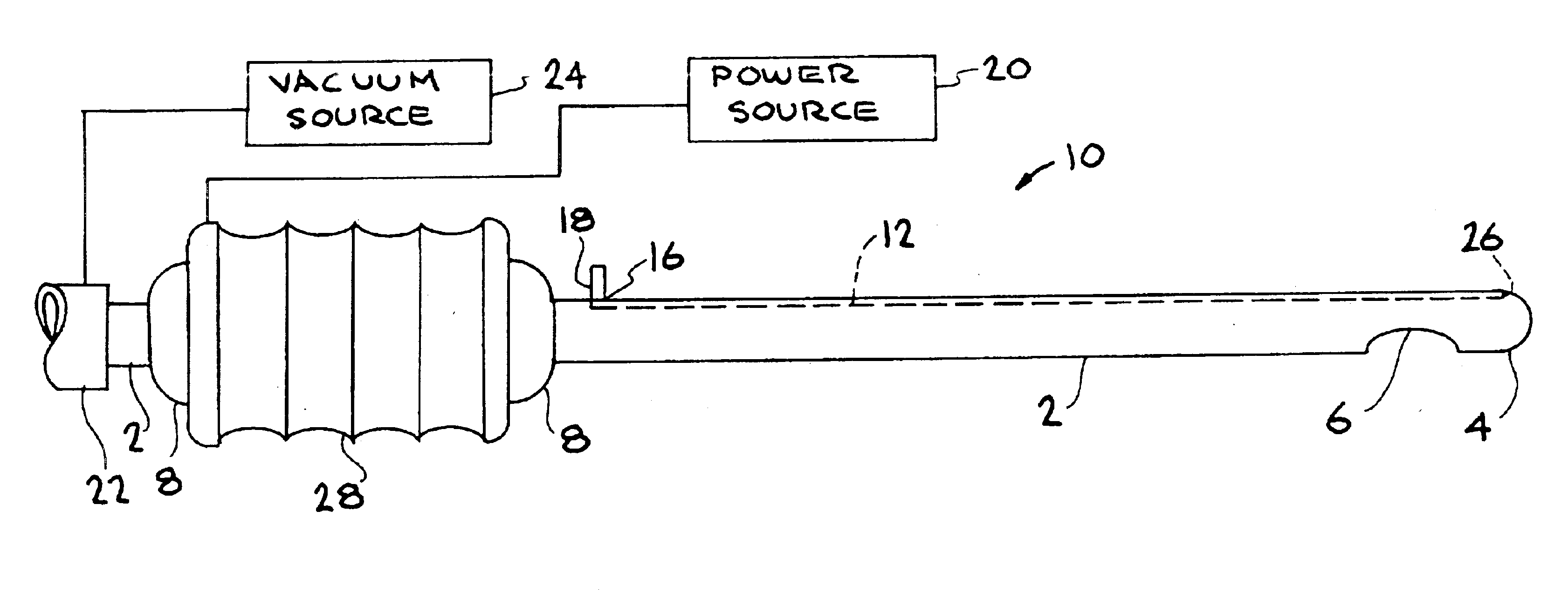
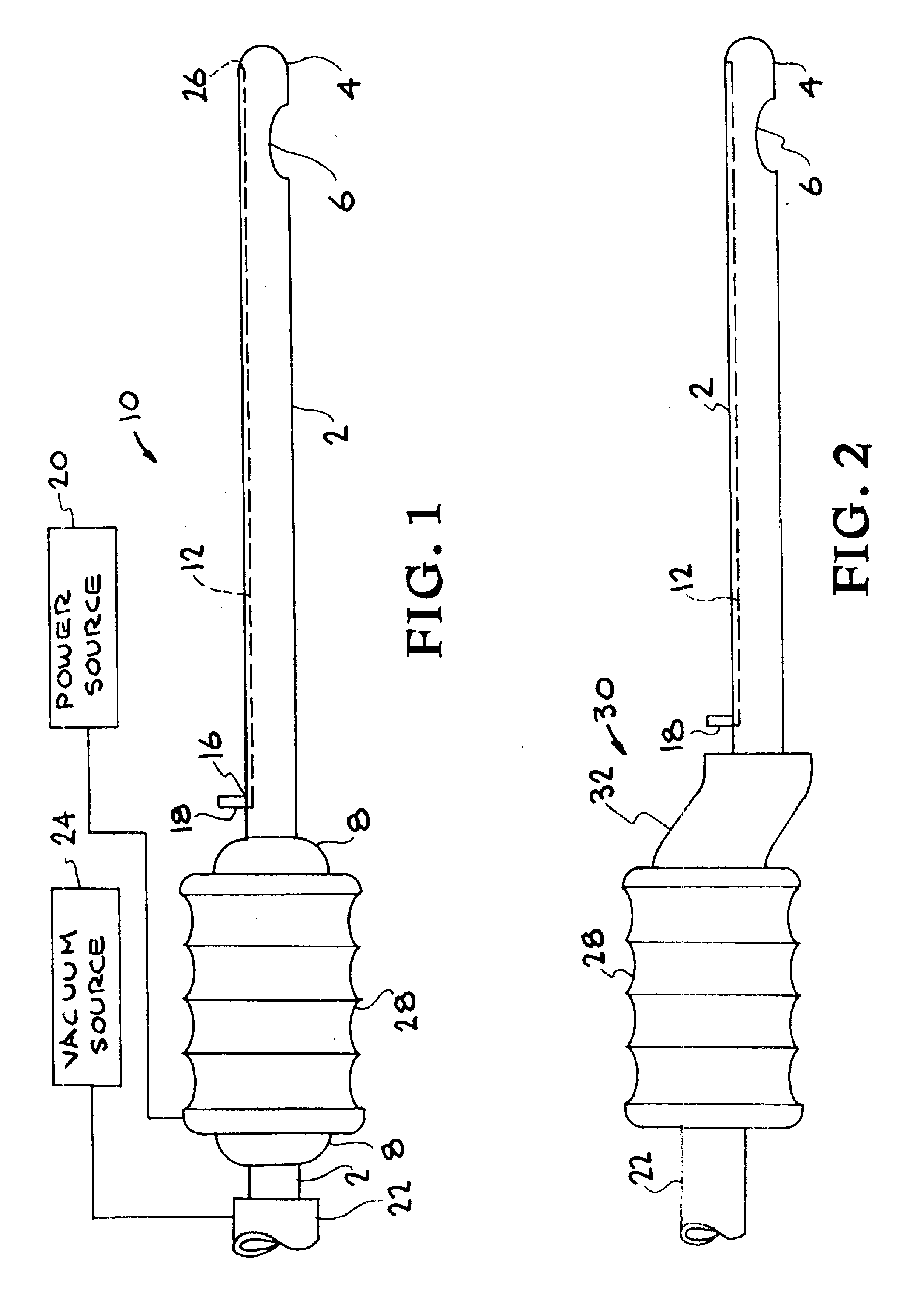
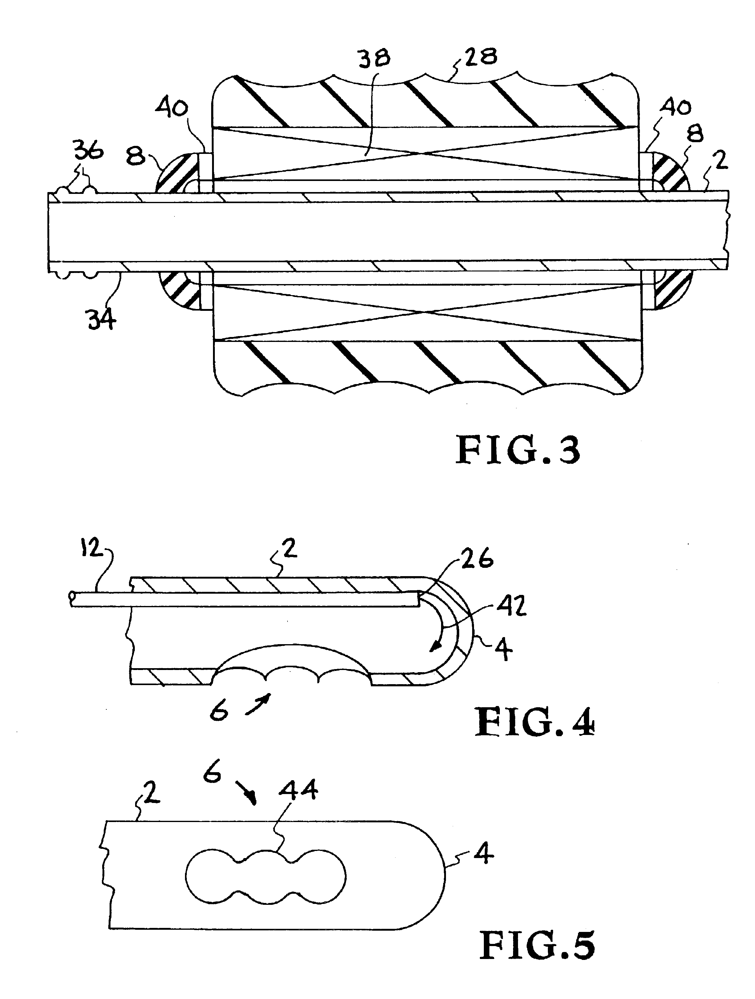
The present invention is directed to a reciprocating liposuction cannula apparatus or device which utilizes a single cutting shaft, may utilize a combination of reciprocating energy and ultrasonic energy, and may utilize available excess (over that required for suction) vacuum (negative pressure) capacity to produce the reciprocation of the cannula shaft, One embodiment of this invention uses a single shaft for cutting, preferably in a non-rectilinear oscillation motion. An additional lumen may be utilized for cooling of the cannula tip, equilibrating the pressure, or providing additional pressure to allow fat to move back up the cannula shaft with greater ease. The combination of reciprocating energy and ultrasonic energy reduces the total energy of each type. Also, in this non-rectilinear reciprocating form of the cannula device, no protective measures (monitoring tip impact) need be taken in order to prevent the device from battering through important organs.

The combination of ul...


PUM


Abstract

A liposuction apparatus and method optionally having a sonic or ultrasonic source with an axial lumen passage in which the shaft can be made to reciprocate (oscillate) in a non-rectilinear fashion. The apparatus may also contain the concomitant use of rectilinear reciprocation motion in addition to ultrasonic motion or energy along the shaft of the apparatus. The advantages of the liposuction apparatus are as follows: 1) non-rectilinear single shaft reciprocating cannula, 2) sonic or ultrasonic energy delivered to the distal tip, 3) rectilinear reciprocating cannula with ultrasonic energy along the shaft from the handle, and 4) any of the above reciprocating components powered by excess unused vacuum capacity in the liposuction aspirator (suction engine) apparatus. There are three (3) primary sources of energy applied to the cannula shaft: the first is the oscillating surgeon's arm motion (approximately 1-2 hertz); the reciprocating motion (of about 100 Hz); and the optional concomitant motion as delivered by the ultrasonic energy (e.g. 25 KHz).

Description

BACKGROUND OF THE INVENTION1. Field of the InventionThis invention relates to a liposuction apparatus and method. More particularly, this invention relates to a liposuction apparatus optionally having a sonic or ultrasonic source with an axial lumen passage in which the shaft can be made to reciprocate in a non-rectilinear fashion. The apparatus and method may also contain the concomitant use of rectilinear reciprocation motion in addition to ultrasonic motion or energy along the shaft of said device.2. Description of the Prior ArtLiposuction, which literally means “fat suction”, is a technique to remove intact fat cells, fat globules, fatty fluids or fatty debris from the body by means of teasing, pulling, scraping, sonication, suction and / or pressing out the debris. Liposuction can be used to reduce the volume of fat in many regions of the body, but liposuction is particularly effective in such areas as the thighs and the abdomen where fat is less responsive to diet and exercise. ...

Claims


Application Information

Patent Timeline
IPC IPC(8): A61B17/32A61M1/00
CPCA61B17/32002A61B17/320068A61B2017/00738Y10S604/902A61M1/008A61M2202/08A61B2217/005A61B2017/32007A61M1/89A61M2205/106A61M2205/103A61M1/842
Inventor WEBER, PAUL J.VISURI, STEVEN R.EVERETT, MATTHEW J.DA SILVA, LUIZ B.KOLSTER, ALWIN H.
Owner LAWRENCE LIVERMORE NAT SECURITY LLC
Learn More