
Dry toner, toner production process, image forming method and process cartridge

a technology of toner production process and cartridge, applied in the field of toner, can solve the problems of affecting the resultant image quality, unable to realize an excellent image forming apparatus, and uniformly increasing the transfer efficiency of all toner particles, and achieves the effect of less waste of toner and high transfer efficiency

Inactive Publication Date: 2005-04-05
CANON KK
View PDF45 Cites 41 Cited by
  • Summary
  • Abstract
  • Description
  • Claims
  • Application Information

AI Technical Summary

Benefits of technology

A more specific object of the present invention is to provide a toner showing a high transfer efficiency and thus resulting in less waste toner.

Problems solved by technology

A developing method using an insulating magnetic toner involves an unstable factor associated with the use of such an insulating magnetic toner.
These difficulties are presumably caused by the presence at the magnetic toner particle surfaces of fine particles of magnetic material having a lower resistivity than the resin constituting the toner.
The toner chargeability also greatly affects the developing performance and transferability, thus also deeply affecting the resultant image quality.
Consequently, a toner is required to exhibit higher performances, failure of which makes impossible the realization of an excellent image forming apparatus.
This problem is encountered also in the case of storing the waste toner in a vessel or a recovery box disposed in the apparatus or in a system including a waste toner recovery unit integral with the photosensitive member.
However, a toner produced through the pulverization process is caused to have a generally broad particle size distribution, so that it is difficult to uniformly increase the transfer efficiency of all the toner particles, thus leaving a room for further improvement.
However, these toner production methods require a large production apparatus, and the resultant sphere-like toner particles are liable to cause a problem of cleaning failure because of their spherical shape.
However, the thus-improved transfer efficiency is still insufficient in an image forming system for achieving versatile functions, higher speed, higher image qualities and machine size reduction for image forming machines inclusive of copying machines, printers and facsimile apparatus.
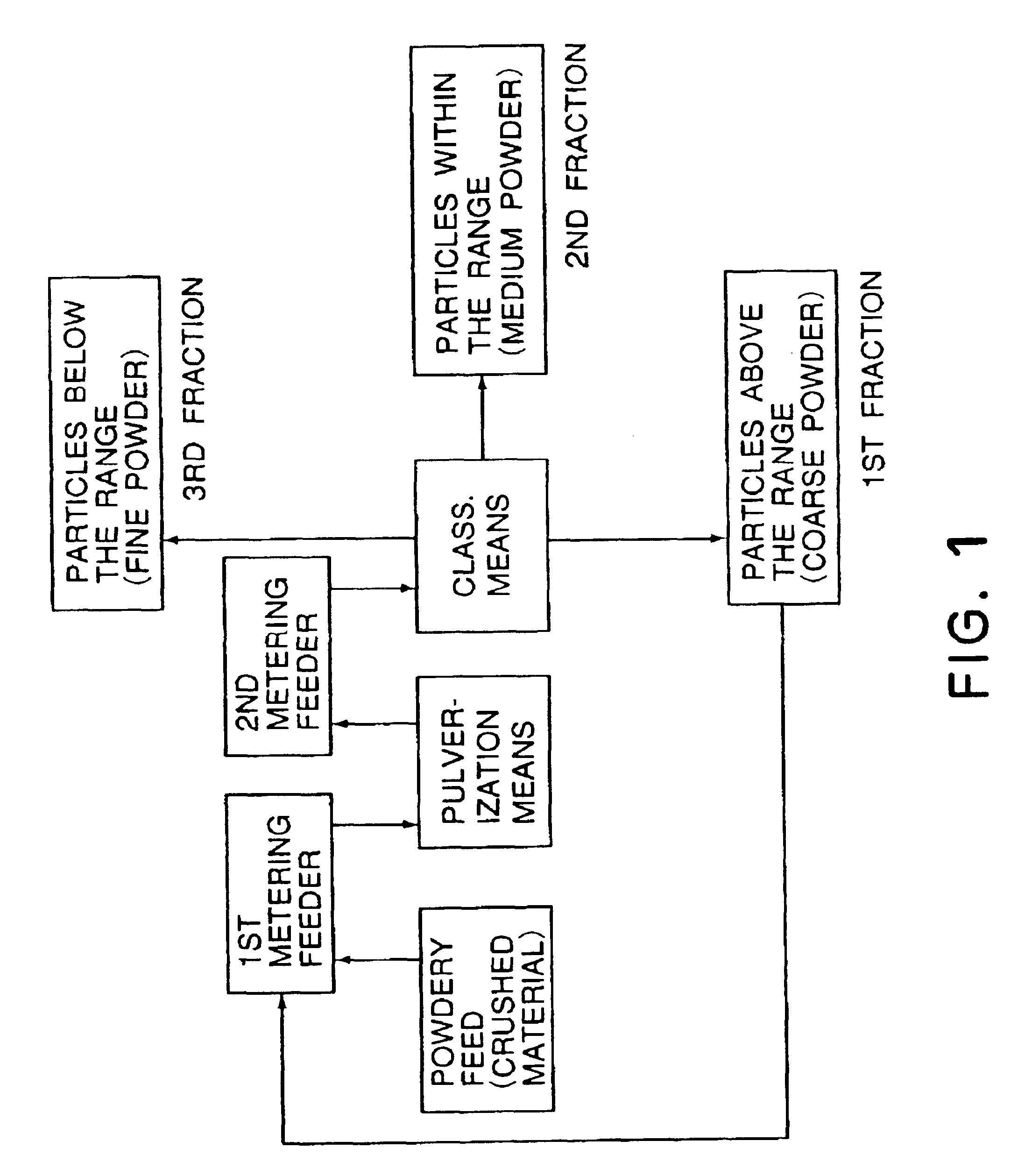
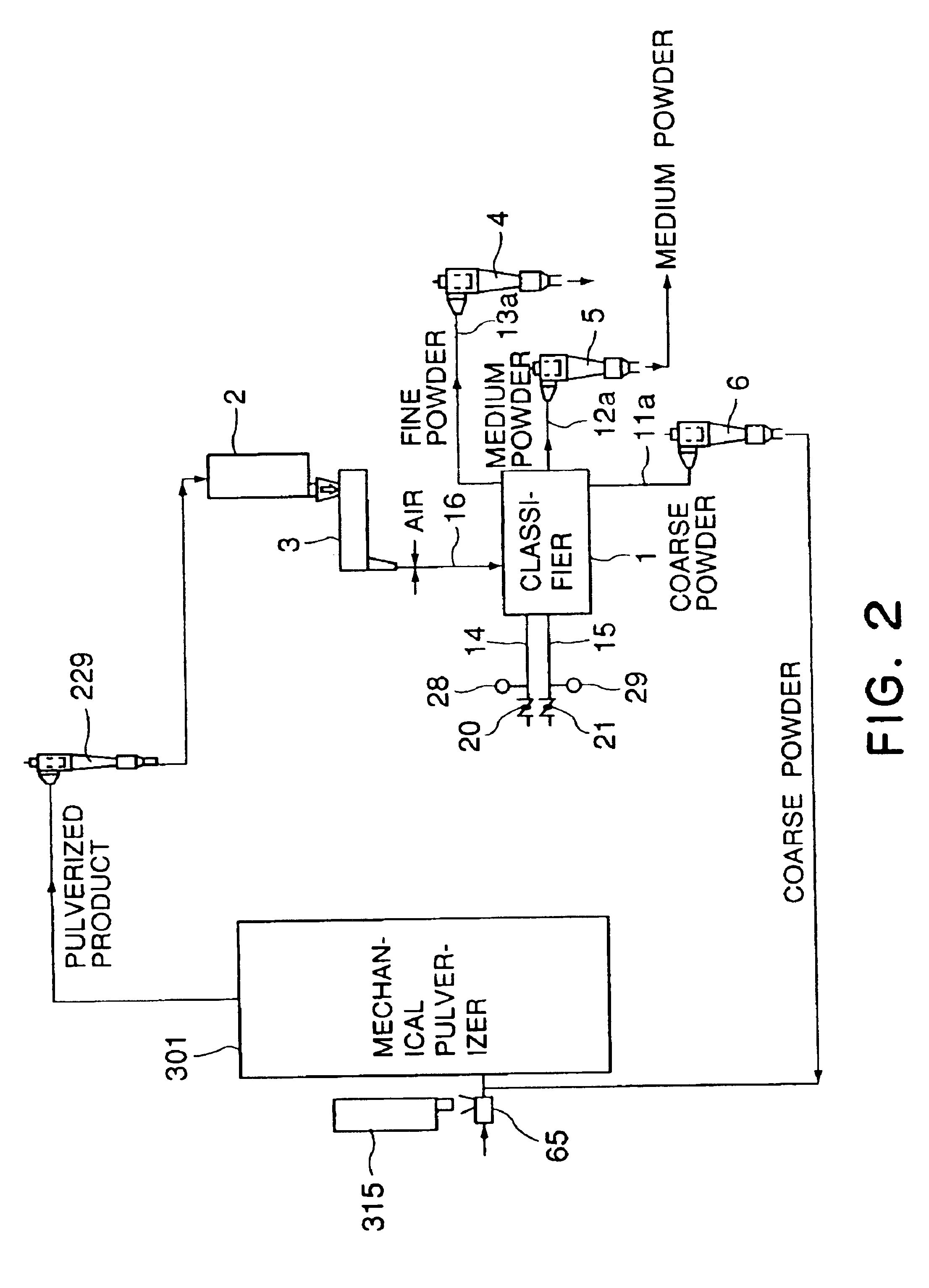
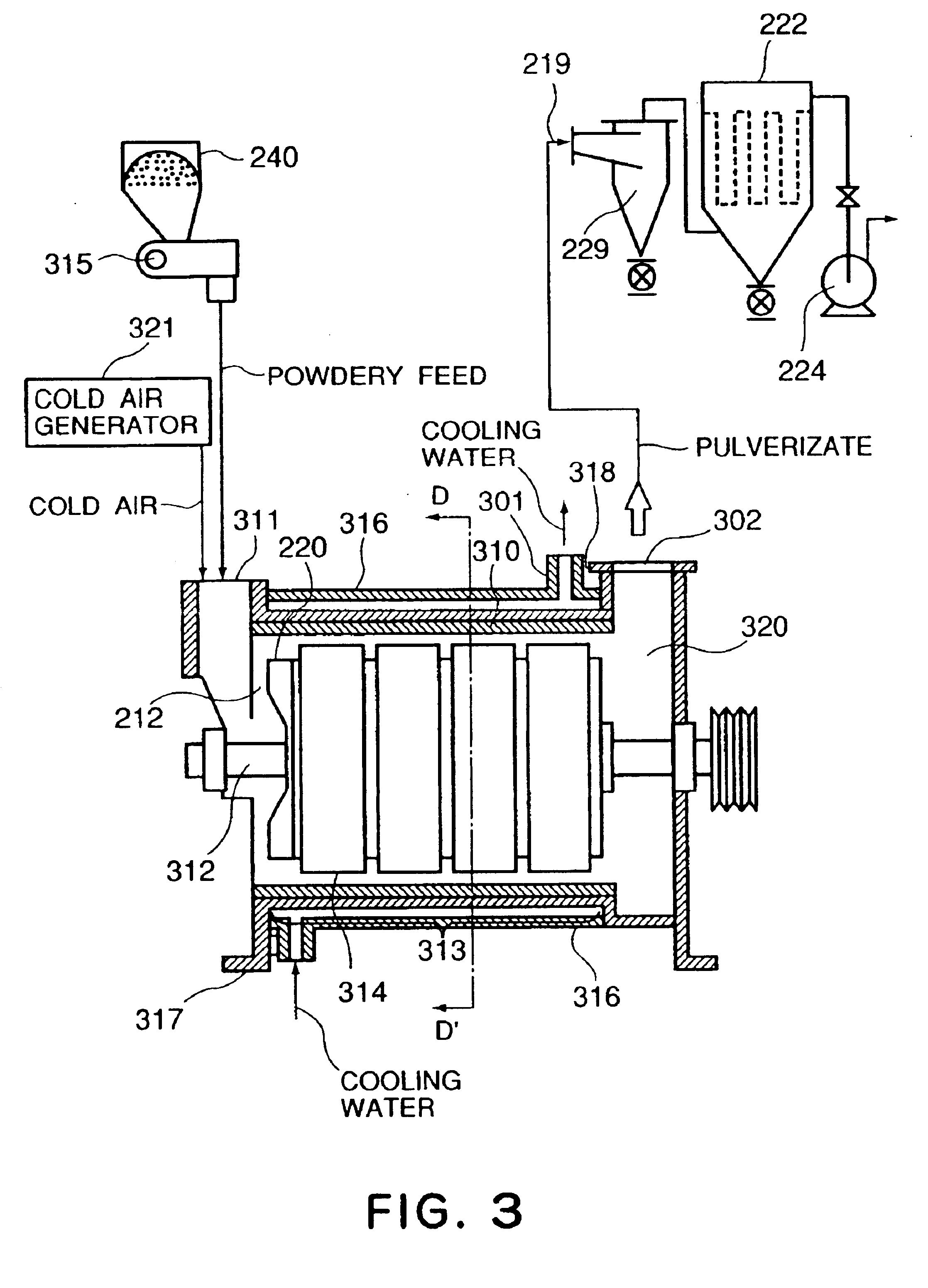
However, as the powdery material is pulverized by the impacting force caused by the impingement of the powder ejected together with a high-pressure gas onto the impingement member, the resultant toner particles are made indefinitely shaped and angular, and the release agent and magnetic material powder are liable to be isolated from the toner particles.
Further, in order to produce a small particle size toner by using the above-mentioned impingement-type pneumatic pulverizer, a large amount of air is required, thus increasing the electric power consumption which results in an increase in production energy cost.
The respective powder streams are liable to flow separately and be ejected in different courses depending on positions of introduction into the classifying chamber, and further the coarse powder stream is liable to disturb the course of flying of fine powder, thus posing a limit of improved classification accuracy.
Further, according to the conventional system, even if a toner product having an accurate particle size distribution can be attained, the steps therein are liable to be complicated to result in a lower classification efficiency, a lower production yield and a higher production cost.
As a result, in order to comply with a higher process speed, the lowering in low-temperature fixability and restriction on developing performance of a magnetic toner become severer than ever.

Method used


Image

  • Dry toner, toner production process, image forming method and process cartridge
  • Dry toner, toner production process, image forming method and process cartridge
  • Dry toner, toner production process, image forming method and process cartridge

Examples


production example 1

Into a ferrous sulfate aqueous solution, an aqueous solution of sodium hydroxide in an amount of 0.95 equivalent to Fe2+ in the ferrous sulfate solution was added and mixed therewith to form a ferrous salt aqueous solution containing Fe(OH)2. Then, sodium silicate containing 1.0 wt. % of silicon (Si) based on the iron in the ferrous salt solution was added thereto. Then, air was blown into the ferrous salt solution containing Fe(OH)2 and silicon at 90° C. to cause oxidation at pH 6 to 7.5, thereby forming a suspension liquid containing silicon (Si)-containing magnetic iron oxide particles. Into the suspension liquid, an aqueous solution of hydroxide in an amount of 1.05 equivalent to Fe2+ remaining in the slurry and containing sodium silicate including 0.1 wt. % of silicon (Si) based on the iron was added, and oxidation was continued under heating at 90° C. and at pH 8-11.5 to obtain Si-containing magnetic iron oxide particles, which were then washed, recovered by filtration and dri...

production examples 2 to 5

Magnetic iron oxide particles (2) to (5) shown in Table 3 were respectively prepared in the same manner as in Production Example 1 except for changing the amounts of silicone (Si) as shown in Table 3, respectively.

TABLE 1Binder resinsMonomersBinderRatioMwMnMw / MnAcid valueTgresinSpecies *1parts (or mol)(×104)(×104)(—)(mgKOH / g)(° C.)ASt78.030.11.127.42.259.8nBA20.0MnBM1.5DVB0.5BSt74.531.90.7542.52060.2nBA20.0MnBM5DVB0.5CTPA28 (mol)8.50.6413.39.257.8TMA 6 (mol)DDSA16 (mol)POBPA50 (mol)DSt79.525.50.8729.00.159.4nBA20.0DVB0.5*1 St = styrene, nBA = n-butyl acrylate MnBM = mono-n-butyl maleate, DVB = divinylbenzene TPA = terephthalic acid, TMA = trimellitic anhydride DDSA = dodecenylsuccinic acid, POBPA = propoxy-bisphenol A

TABLE 2WaxesWaxspeciesTabs·max (° C.)(a)polypropylene140 (b)polyethylene80(c)paraffin73(d)Fischer-Tropsche110 

TABLE 3Magnetic iron oxide particlesSiMagnetic ironD1contentSBEToxide particles(μm)(%)(m2 / g)(1)0.211.0910.0(2)0.210.809.7(3)0.210.2510.3(4)0.202.4015.1(5)0.211...

example 1

Toner No. 1 prepared above was incorporated in a process cartridge of an image forming apparatus having an organization as shown in FIG. 14 obtained by re-modeling a commercially available laser beam printer (“LBP-250”, made by Canon K.K.) so as to include a cleanerless image forming system as described with reference to FIG. 14. Image-forming performances of Toner No. 1 were evaluated by printing on 5000 sheets while replenishing the toner, as required, in each of low temperature / low humidity environment (15° C. / 10% RH), normal temperature / normal humidity environment (23.5° C. / 60% RH) and high temperature / high humidity environment (30° C. / 80% RH). The evaluation was performed with respect to the following items.

Image density (ID) was measured in terms of a reflection density with respect to a 5 mm-square solid image by means of a Macbeth densitometer (available from Macbeth Co.) with an SPI filter.

Fog was determined by measuring a highest reflection density Ds of a white background...


PUM


Abstract

A toner showing a high transferability and suitable for use in cleanerless image forming system is formed of toner particles comprising at least a binder resin and magnetic iron oxide. The toner is characterized by a specific circularity distribution relative to its weight-average particle size and a controlled degree of surface-exposed magnetic iron oxide providing an extract solution with hydrochloric acid showing an absorbance of 1.0-2.5 at a wavelength of 340 nm. The toner is suitably produced by a production system including a rotary mechanical pulverizer and a one-pass surface treatment apparatus for continuously applying a mechanical impact force to pulverized toner particles therein.

Description

FIELD OF THE INVENTION AND RELATED ARTThe present invention relates to a toner for use in electrophotography, an image forming method for visualizing an electrostatic image and toner jetting; a process for producing the toner, an image forming method using the toner, and a process cartridge including the toner.A developing method using an insulating magnetic toner involves an unstable factor associated with the use of such an insulating magnetic toner. More specifically, insulating magnetic toner particles contain a substantial amount of fine powdery magnetic material, and a portion of the magnetic material is isolated from or exposed to the surfaces of the toner particles, thus affecting the flowability and triboelectric chargeability of the magnetic toner to consequently change or deteriorate the various performances, inclusive of developing performance and continuous image forming performances. These difficulties are presumably caused by the presence at the magnetic toner particl...

Claims


Application Information

Patent Timeline
Patent Type & Authority Patents(United States)
IPC IPC(8): G03G9/083G03G9/08
CPCG03G9/081G03G9/0815G03G9/0833G03G9/0821G03G9/0827G03G9/0819
Inventor YAMAZAKI, KATSUHISATANIKAWA, HIROHIDEYUSA, HIROSHIKASUYA, TAKASHIGEOGAWA, YOSHIHIROMORIBE, SHUHEI
Owner CANON KK
Learn More