Residue number system arithmetic circuits with built-in self test

a number system and arithmetic circuit technology, applied in the field of electronic circuits, can solve the problems of other operations, base extension, and the effect of reducing the speed of the circuit, and achieve the effect of simple circuitry

Inactive Publication Date: 2005-04-26
STMICROELECTRONICS SRL
View PDF10 Cites 4 Cited by
  • Summary
  • Abstract
  • Description
  • Claims
  • Application Information

AI Technical Summary

Benefits of technology

[0023]Another object of the present invention is to provide RNS arithmetic circuits that have simple circuitry for performing built-in self testing of input-to-output delay.

Problems solved by technology

The ultra-low power circuits of the future will have to employ several of these approaches because none alone can achieve the power reduction goals for the next decade.
While all of the techniques described above advantageously reduce power consumption, many of them have a deleterious side effect of reducing the speed of the circuit.
However, other operations such as magnitude comparison, scaling (the RNS equivalent of right shifting), base extension (the RNS equivalent of increasing the bit width), and division are slower and more complicated to implement.
This is the minimal possible activity factor and yields low power dissipation.
While offering such advantageous characteristics and a very low delay-power product, conventional RNS arithmetic circuits are not testable.
In particular, conventional RNS arithmetic circuits do not include simple test circuitry to allow verification of circuit functionality and timing.

Method used


Image

  • Residue number system arithmetic circuits with built-in self test
  • Residue number system arithmetic circuits with built-in self test
  • Residue number system arithmetic circuits with built-in self test

Examples


Embodiment Construction

[0035]Preferred embodiments of the present invention will be described in detail hereinbelow with reference to the attached drawings.

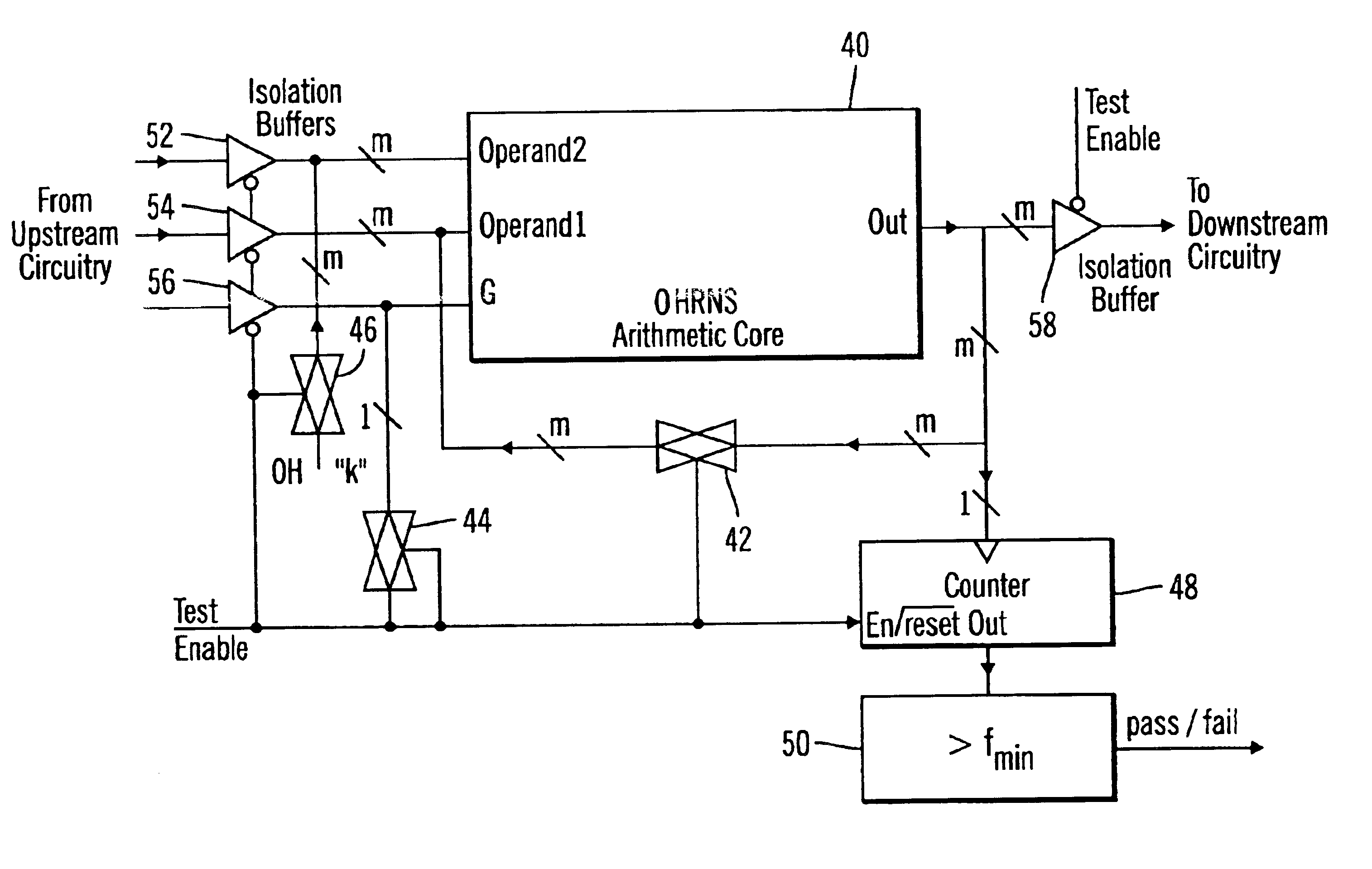
[0036]The core circuits used to perform OHRNS arithmetic operations have the advantageous property that input-to-output timing is identical for all inputs and outputs. The present invention takes advantage of this property to enable verification of the timing of the circuit with simple built-in self test circuitry. In preferred embodiments, the input-to-output delay of an OHRNS arithmetic circuit is tested using Oscillation Built-In Self Test (OBIST). More specifically, the circuit is made to oscillate by feeding the output back to the input, and the frequency of oscillation of the circuit is measured. Because the frequency of oscillation is inversely proportional to the input-to-output delay of the circuit, the measured frequency can be used to ascertain whether or not the delay of the circuit is within specification. (A general explanation of OBIST c...


PUM


Abstract

An arithmetic circuit for use with an RNS is provided. The arithmetic circuit includes an arithmetic core, test circuitry, and logic circuitry. The arithmetic core performs an RNS arithmetic operation, and the test circuitry verifies proper circuit delay by inducing oscillation at the output of the arithmetic core during testing. The logic circuitry produces a pass/fail signal based on whether the oscillation frequency of the arithmetic core is at least equal to a minimum threshold value. In one preferred embodiment, the logic circuitry includes a counter that counts oscillations of the output of the arithmetic core during testing, and a comparator that compares the output of the counter after a predetermined test period with the minimum threshold value. Also provided is a method for testing the propagation delay of an RNS arithmetic circuit having an arithmetic core.

Description

BACKGROUND OF THE INVENTION[0001]1. Field of the Invention[0002]The present invention relates to electronic circuits, and more specifically to arithmetic circuits having built-in self testing for use with the residue number system.[0003]2. Description of Related Art[0004]Power consumption is now a very important consideration in integrated circuit design. This has compelled circuit designers to consider reducing power consumption through changes in many different levels of the design process, such as the system, technology, algorithm, physical, and circuit levels. For example, system level approaches for reducing power consumption include power supply voltage scaling, clock gating, and subsystem sleep (or power down) modes. Technology level techniques include using dynamic threshold MOSFETs, and algorithm level techniques include using alternate number systems and state encoding. Further, physical level methods include transistor reordering, and circuit level methods include self-ti...

Claims


Application Information

Patent Timeline
Patent Type & Authority Patents(United States)
IPC IPC(8): G01R31/28G01R31/30
CPCG01R31/3016
Inventor CHREN, JR., WILLIAM A.
Owner STMICROELECTRONICS SRL
Why Eureka
Try Eureka