Method and apparatus for using adaptive optics in a scanning laser ophthalmoscope

a scanning laser and adaptive optics technology, applied in the field of scanning laser ophthalmoscopes, can solve the problems of limited resolution at the microscopic level, propose a wavefront sensing method, and cannot apply the technology to a slo, so as to reduce aberrations of the eye, improve axial and lateral resolution, and reduce aberrations

Inactive Publication Date: 2005-05-10
UNIVERSITY OF ROCHESTER
View PDF14 Cites 81 Cited by
  • Summary
  • Abstract
  • Description
  • Claims
  • Application Information

AI Technical Summary

Benefits of technology

[0014]To achieve the above and other objects, the present invention is directed to a system and method whereby AO can be efficiently and effectively implemented in a scanning laser ophthalmoscope. The present invention will be an improvement on instruments used to take microscopic images of the retina in living human eyes and will have improved optical sectioning capability over currently available SLO's.
[0040]The SLO can use a confocal pinhole to suppress light from outside of the focal plane, which gives the SLO its optical slicing capability. This property of the SLO can be improved by implementing AO to measure and correct the aberrations of the eye. By reducing the aberrations of the eye through AO compensation, both axial and lateral resolution can be improved.

Problems solved by technology

A scanning laser ophthalmoscope for high lateral-resolution imaging was developed which was capable of imaging a living human eye but did not use adaptive optics (AO) and had limited resolution at the microscopic level.
A 14, 2884-2892 (1997), used an ophthalmoscope equipped with AO to image microscopic structures in the retina, but they did not apply the technology to a SLO.
Although there are a number of patents covering SLO's, they do not propose a method for wavefront sensing whereby the light path is scanned / descanned using the same optics and light source as that used for imaging the ocular fundus.
Methods that do not use the same optics for wavefront sensing and light detection are subject to a common phenomena called “non-common path errors,” where the aberrations on the path to the wavefront sensor are different than those reaching the light detector for imaging.
However, areal imaging techniques are limited in that they cannot suppress light from layers in front of or behind the focal plane of the ophthalmoscope.
Because of this limitation, the images may have high resolution, but will suffer from low contrast because of scattered light from structures outside of the best focal plane.
To date, there has been no successful application of AO into a SLO.
Bille's above-cited patent describes a design for a SLO that integrates a wavefront sensor into the design, but it does not use the same path as the light detection path and is therefore subject to the problem of non-common path errors.

Method used


Image

  • Method and apparatus for using adaptive optics in a scanning laser ophthalmoscope
  • Method and apparatus for using adaptive optics in a scanning laser ophthalmoscope
  • Method and apparatus for using adaptive optics in a scanning laser ophthalmoscope

Examples


Embodiment Construction

[0051]A preferred embodiment of the present invention and variations thereof will now be set forth in detail with reference to the drawings, in which like reference numerals refer to like elements or operational steps throughout.

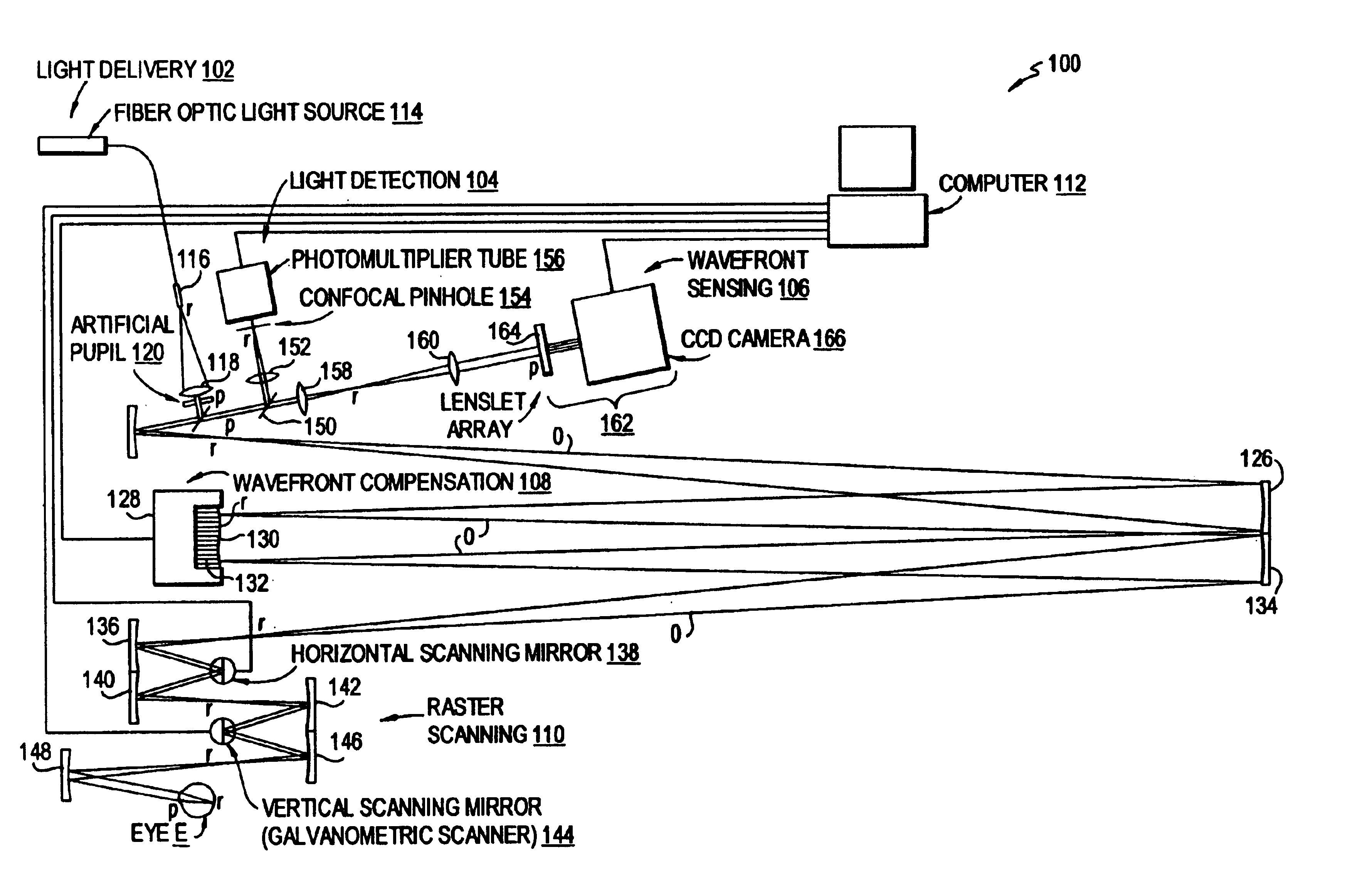
[0052]FIG. 1 shows a schematic diagram of the scanning laser ophthalmoscope using adaptive optics (AOSLO). In FIG. 1, points on the optical path which are conjugate to the pupil of the eye are labeled p, while points on the path that are conjugate to the retina are labeled r.

[0053]As mentioned above, the AOSLO 100 includes a light delivery section 102, a light detection section 104, a wavefront sensing section 106, a wavefront compensation section 108 and a raster scanning section 110. All five sections are under the control of a computer 112.

[0054]In the light delivery section 102, light from a fiber optic light source 114 is expanded by a beam expander 116 and collimated by a collimating lens 118. The collimated light is made incident on an artificial pupi...


PUM


Abstract

A scanning laser ophthalmoscope incorporates adaptive optics to compensate for wavefront aberrations in the eye. Light from a light source is scanned onto the retina. Light reflected from the retina is detected for imaging and is also used for wavefront sensing. The sensed wavefront aberrations are used to control an adaptive optic device, such as a deformable mirror, disposed in the path of the light from the source in order to compensate for the aberrations.

Description

REFERENCE TO RELATED APPLICATION[0001]The present application claims the benefit of U.S. Provisional Application No. 60 / 316,173, filed Aug. 30, 2001, whose disclosure is hereby incorporated by reference in its entirety into the present disclosure.STATEMENT OF GOVERNMENT INTEREST[0002]The present invention was developed under NIH Grant No. R1 EY 13299-01 and NSF Grant No. AST 9876783. The government has certain rights in the invention.FIELD OF THE INVENTION[0003]The present invention is directed to scanning laser ophthalmoscopes (SLO) and methods of using them, and more particularly to such ophthalmoscopes and methods of using them which involve the use of adaptive optics (AO) to compensate for wavefront aberrations in the eye under examination.DESCRIPTION OF RELATED ART[0004]The development of ocular imaging has progressed since the first scanning laser ophthalmoscope (SLO) was disclosed in U.S. Pat. No. 4,213,678. The first patent relating to imaging the ocular fundus while correct...

Claims


Application Information

Patent Timeline
Patent Type & Authority Patents(United States)
IPC IPC(8): A61B3/12A61B3/113A61B3/10G01J9/00G02B26/06
CPCG01J9/00A61B3/1025G02B26/06
Inventor ROORDA, AUSTIN
Owner UNIVERSITY OF ROCHESTER
Why Eureka
Try Eureka