Domain wall-displacement type magneto-optical medium and reproducing method for the same

Inactive Publication Date: 2005-05-17
CANON KK
View PDF23 Cites 14 Cited by
  • Summary
  • Abstract
  • Description
  • Claims
  • Application Information

AI Technical Summary

Benefits of technology

[0019]In view of the above identified circumstances, it is therefore the object of the present invention to provide a magneto-optical recording medium adapted to reproduce information, utilizing displacement of a doma

Problems solved by technology

However, it is not easy to reduce the laser wavelength from the viewpoint of operating efficiency of devices and the problem of generation of heat.
However, the above proposed signal reproduction method has a drawback that the region that is effectively used for signal detection and signal retrieval is smaller than the spot diameter of the signal reproducing laser beam and hence the reproduced signal shows

Method used


Image

  • Domain wall-displacement type magneto-optical medium and reproducing method for the same
  • Domain wall-displacement type magneto-optical medium and reproducing method for the same
  • Domain wall-displacement type magneto-optical medium and reproducing method for the same

Examples


example 1

[0075]FIG. 4 is schematic cross sectional view of the magneto-optical recording medium of Example 1, illustrating the basic multilayer structure thereof. Like the magneto-optical recording medium described above by referring to FIG. 1A, this magneto-optical recording medium comprises a bottom layer 9, a magnetic layer 1 that is a domain wall displacement layer, another magnetic layer 2 that is a switching layer, still another magnetic layer 3 that is a recording layer and a surface layer 10 laid sequentially on a substrate 8.

[0076]The substrate 8 is typically made of polycarbonate or glass. In this example, a land / groove recording type glass 2P substrate having a track pitch of 0.6 μm and a groove depth of about 180 nm was used for the substrate 8. The bottom layer 9 is typically made of a transparent dielectric material such as Si3N4, AlN, SiO2, SiO, ZnS or MgF2. A similar dielectric material may be used for the surface layer 10 that is formed as protection layer. These layers can ...

example 2

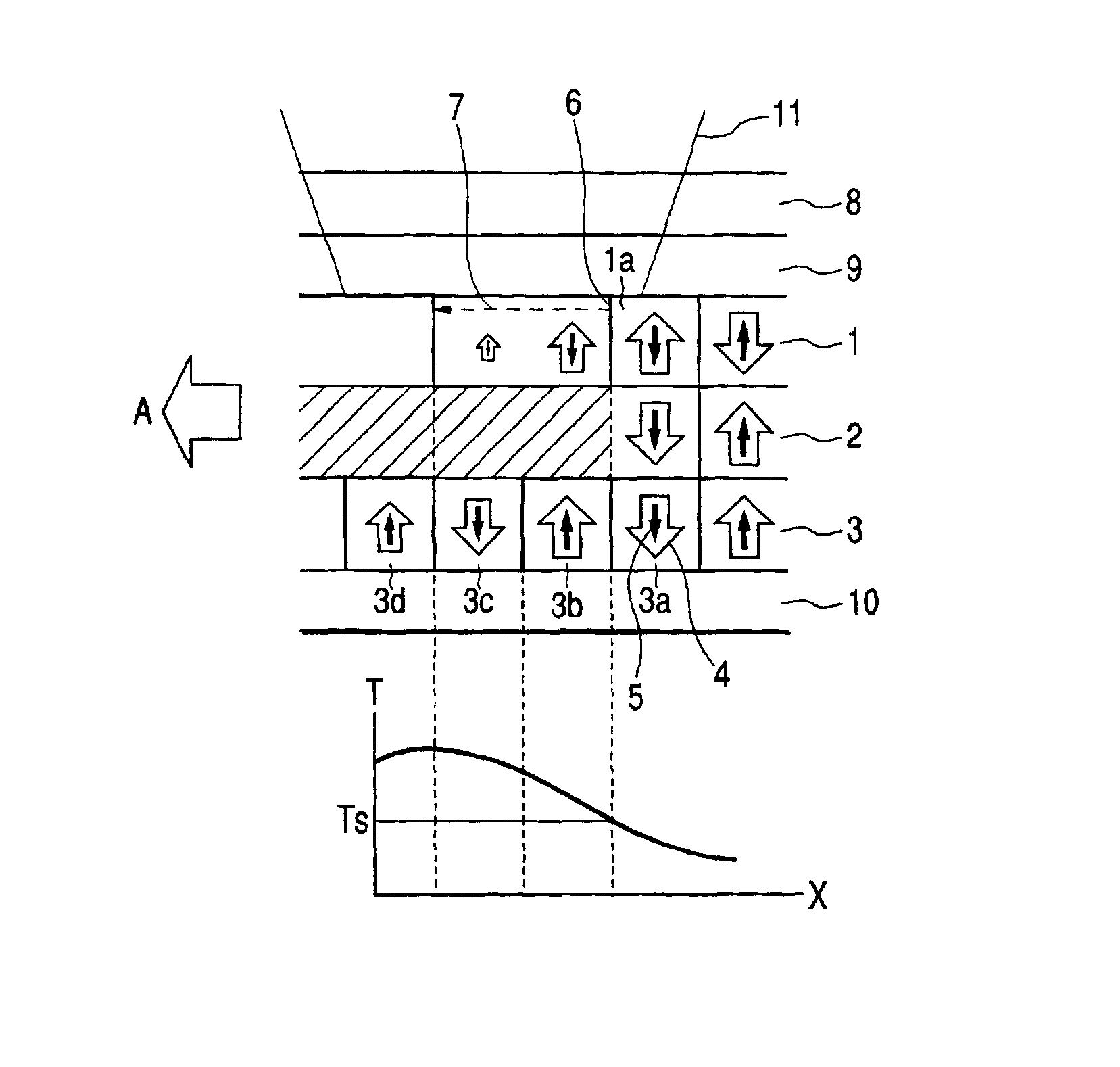
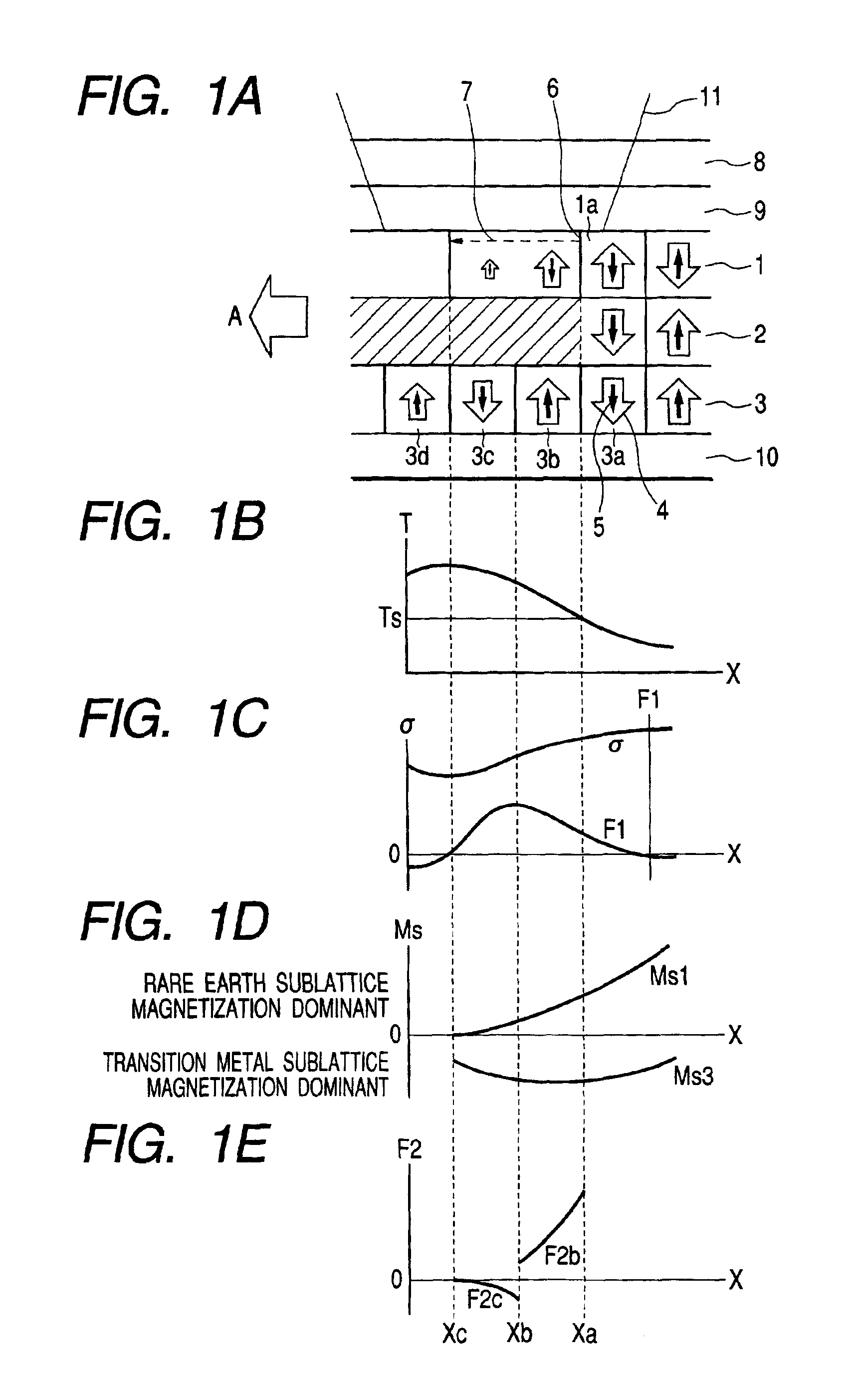
[0084]FIGS. 6A through 6C schematically illustrate the principle of reproducing signals from the magneto-optical recording medium of Example 2. FIG. 6A is a schematic cross sectional view of the magneto-optical recording medium of Example 2, illustrating its configuration and the change in the magnetized state thereof when irradiated with a reproducing light beam and FIG. 6B is a graph illustrating the distribution of the saturation magnetization of the domain wall displacement layer and that of the saturation magnetization of the recording layer corresponding to the temperature distribution produced in the recording medium when irradiated with a reproducing light beam, whereas FIG. 6C is a graph illustrating the distribution of the magnetostatic force generated by the distribution of saturation magnetization of FIG. 6B. In FIG. 6A, the elements that are the same as or similar to those of FIG. 1A are denoted respectively by the same reference symbols.

[0085]The magneto-optical record...

example 3

[0092]The magneto-optical recording medium of this example is identical with that of Example 1 except that the composition of the domain wall displacement layer, that of the switching layer and that of the recording layer were different from those of the specimen of Example 1. More specifically, a composition of Tb0.19Fe0.73Al0.08 was used for the switching layer so as to make its Curie temperature Ts equal to about 130° C. and a composition of Gd0.22Fe0.61Co0.10Al0.07 was used for the domain wall displacement layer to make its Curie temperature Ts equal to about 260° C. and transition metal sublattice magnetization become dominant at and near the Curie temperature Ts (130° C.) of the switching layer, whereas Tb0.25Fe0.52Co0.23 was used for the recording layer to make its Curie temperature Ts equal to about 320° C. and rare earth sublattice magnetization become dominant at and near the Curie temperature Ts (130° C.) of the switching layer.

[0093]The magneto-optical medium of this exa...


PUM

PropertyMeasurementUnit
Temperatureaaaaaaaaaa
Magnetizationaaaaaaaaaa

Abstract

A magneto-optical recording medium has a domain wall displacement layer, a recording layer for accumulating information and a switching layer arranged between said domain wall displacement layer and said recording layer and having a Curie temperature lower than those of the latter two layers. The domain wall displacement layer, the switching layer and the recording layer are coupled by exchange coupling at temperature not higher than the Curie temperature of the switching layer. The saturation magnetization of the domain wall displacement layer and the recording layer are in opposite directions to each other when the layers are coupled by exchange coupling at a temperature close to the Curie temperature of the switching layer.

Description

BACKGROUND OF THE INVENTION[0001]1. Field of the Invention[0002]This invention relates to a magneto-optical medium adapted to reproduce information, utilizing displacement of domain walls by temperature gradient and also to a reproducing method for such a medium.[0003]2. Related Background Art[0004]Various magnetic recording mediums have been marketed as rewritable recording mediums. Particularly, magneto-optical recording mediums to be used for writing magnetic domains to record information there by means of thermal energy of a semiconductor laser and reading the stored information by means of magneto-optical effects are expected to develop into large capacity portable mediums capable of densely storing information in the future. In recent years, there has been an ever-increasing demand for raising the recording density and hence the storage capacity of such magnetic recording mediums in order to accommodate the current trend of digitizing moving images.[0005]Generally, the linear ...

Claims


Application Information

Patent Timeline
IPC IPC(8): G11B11/105G11B11/00G11B11/10
CPCG11B11/10515G11B11/10593Y10T428/31Y10T428/12465G11B11/10
Inventor AOKI, YUKARI
Owner CANON KK
Why Eureka
Try Eureka