Method and device for the regulation of the concentration of metal ions in an electrolyte and use thereof

a technology of electrolyte fluid and metal ions, which is applied in the direction of electrolysis components, normal temperature solutions, melt solutions, etc., can solve the problems of high supply and disposal costs of this method, inability to keep the metal content in the electrolyte fluid easily constant, and the inability to easily destroy the anode material by corrosion, etc., to achieve the effect of reducing the capacity of the metal ion generator, maintenance, and reducing the cost of production

Inactive Publication Date: 2005-05-31
ATOTECH DEUT GMBH
View PDF9 Cites 12 Cited by
  • Summary
  • Abstract
  • Description
  • Claims
  • Application Information

AI Technical Summary

Benefits of technology

[0032]A further advantage of the invention is that the anode slime known from electroplating plants with soluble anodes does not occur. In parts, a ,feed a bleed operation of the plant may nevertheless be useful. This is particularly true when organic and/or inorganic additives in the electrolyte fluid are to be exchanged in the long run. As a result of the partial discard of electrolyte fluid, the content of the oxidized metal ions of the redox system is lowered proportionally. The capacity of the metal ion generator may be reduced by this portion. Accordingly, the metal ion content can also be kept constant by having substances of the redox system in the oxidized form reduced in the metal ion generator and concurrently, by having part of the electrolyte fluid removed from the electroplating plant and replaced by a fresh electrolyte fluid.
[0033]Inert metal electrodes that have been activated with precious metals and/or with mixed oxides, maintained for deposition. The metal deposition solution is continuously conducted from the electroplating plant, e.g., a precipitation tank into the metal ion generator of the invention and from there back again into the electroplating plant. The substances of the redox system that formed in the oxidized form at the main anode in the electroplating plant are reduced again at the metal pieces in the metal ion generator, thereby forming metal ions. Due to the fact that the rate of formation of the substances of the redox system in the reduced form in the metal ion generator can be varied by having the metal pieces provided with a cathodic polarity relative to an auxiliary anode, the rate of formation of the metal ions in the metal ion generator can be regulated. Another oxidation of the reduced substances of the redox system relative to the oxidized substances at the auxiliary anode is largely prevented from taking place in having the anode space surrounding the auxiliary anode separated from the cathode space surrounding the metal pieces. The fluids in the anode space and in the cathode space are largely prevented from mixing so that the reduced substances of the redox system can reach the auxiliary anode to a very little extent only since these substances can reach the auxiliary anode only by diffusion and since the concentration of the substances in the anode space depletes on account of the electrochemical reaction taking place there.
[0034]In regulating the flow of current in the metal ion generator, the production rate of the substances of the redox system in the reduced form and thus subsequently the rate of formation of the metal ions in the metal ion generator is set to a value which is so large that the quantity of metal ions produced per unit time by oxidation with the redox compounds plus the quantity generated by the dissolution of the metal on account of the oxygen from the air entered in the electrolyte fluid equals the quantity of the metal ions used up at the cathode in the electroplating plant. As a result thereof, the total content of ions of the metal to be deposited in the electrolyte fluid remains constant. In using the method according to the invention the desired stationary condition between the formation of metal ions and their consumption is achieved.
[0035]As compared to the invention described in WO 9910564 A2, the further advantage of the inventive meth...

Problems solved by technology

However, the supply and disposal costs for this method are very high.
Additionally, the oxygen also causes the anode material to be destroyed by corrosion.
The problem with the methods and devices mentioned is that the metal content in the electrolyte fluid cannot be kept constant easily.
As a result thereof, the conditions for deposition vary, thus rendering it impossible to achieve reproducible conditions for the electrolytic deposition.
The problem herewith, according to said document, is that the substances of the electrochemically reversible redox system are oxidized at the anode of the secondary cell so that the content of the oxidized species of these substances rises in the fluid.
But since this would entail that large quantities of the fluid would continuously have to be discarded and disposed of, this procedure, which is also known under the name of, feed and bleed method...

Method used


Image

  • Method and device for the regulation of the concentration of metal ions in an electrolyte and use thereof
  • Method and device for the regulation of the concentration of metal ions in an electrolyte and use thereof
  • Method and device for the regulation of the concentration of metal ions in an electrolyte and use thereof

Examples


first embodiment

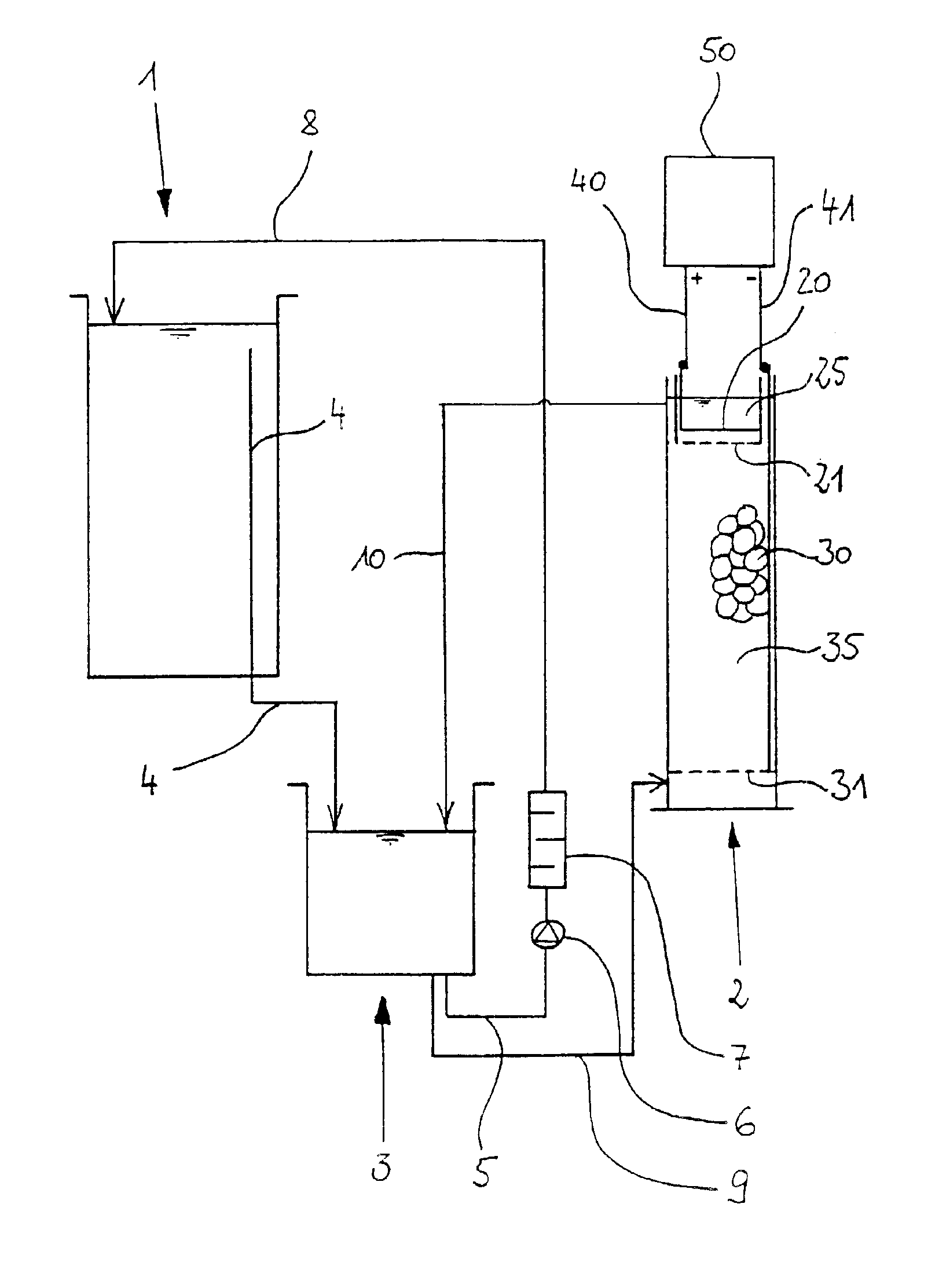
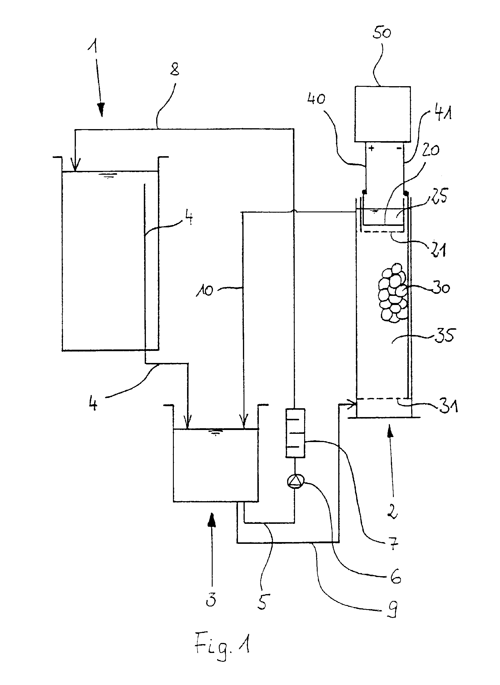
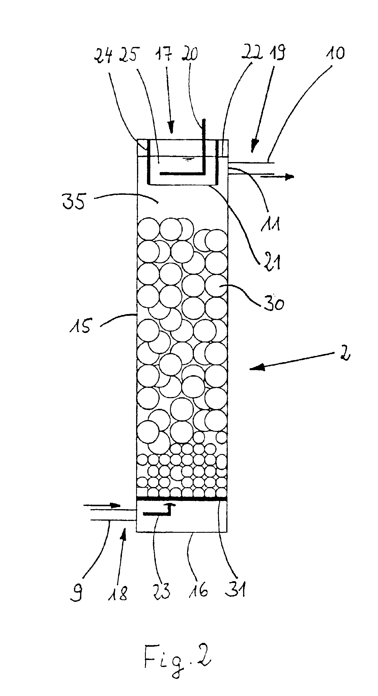
[0056]FIG. 2 shows a section of the metal ion generator 2. The metal ion generator 2 consists of a tubular housing 15 which is made of polypropylene for example and which is provided with a bottom 16 made e.g., of polypropylene too. On its upper front side, the tubular housing 15 is provided with an opening 17. A fluid admission 18 for the electrolyte fluid is provided in the lower region of the tubular housing 15. Correspondingly, a fluid outlet 19 is arranged in the upper region. The cross section of the tubular housing 15 is preferably rectangular, square or circular.

[0057]In the metal ion generator 2 there are located an anode space 25 and a cathode space 35.

[0058]The anode space 25 and the cathode space 35 are separated from each other by a wall 24 and by an ion permeable woven cloth 21, a polypropylene cloth in this case, that is fastened to the lower border of the wall 24. This is shown in detail in FIG. 3. As a result, the convective transport of fluid between the two spaces...

second embodiment

[0062]FIG. 4 shows the metal ion generator 2 according to the invention. In this case, the metal ion generator 2 is a receptacle with side walls 15 which form a rectangular, square or circular ground plan of the metal ion generator 2. The receptacle is furthermore provided with a bottom 16. The walls 15 and the bottom 16 are made of polypropylene. The metal ion generator 2 forms an opening 17 at its top.

[0063]The metal ion generator 2 again is provided with a cathode space 35 and an anode space 25. Furthermore, the spaces 25 and 35 are separated from each other by an ion permeable wall 21, an ion exchange membrane in this case, preferably an anion exchange membrane, which is vertically arranged. A perforated wall 26 is also provided, which endows the membrane with the required stability.

[0064]A sieve bottom 31 is arranged in the lower region in the cathode space 35, said sieve bottom being constituted by a titanium net. A bulk of metal pieces 30 (shown only in parts) rests on the si...


PUM

PropertyMeasurementUnit
Concentrationaaaaaaaaaa
Ratioaaaaaaaaaa
Currentaaaaaaaaaa

Abstract

In order to regulate the metal ion concentration in an electrolyte fluid serving to electrolytically deposit metal and additionally containing substances of an electrochemically reversible redox system, it has been known in the art to conduct at least one portion of the electrolyte fluid through one auxiliary cell provided with one insoluble auxiliary anode and at least one auxiliary cathode, a current being conducted between them by applying a voltage. Accordingly, excess quantities of the oxidized substances of the redox system are reduced at the auxiliary cathode, the formation of ions of the metal to be deposited being reduced as a result thereof. Starting from this prior art, the present invention relates to using pieces of the metal to be deposited as an auxiliary cathode.

Description

BACKGROUND OF INVENTION[0001]1. Field of Invention[0002]The invention relates to a method and a device for regulating the metal ion concentration in an electrolyte fluid. The method and the device may particularly be used for regulating the copper ion concentration in a copper deposition solution that serves to electrolytically deposit copper and that additionally contains Fe(II) and Fe(III) compounds.[0003]2. Brief Description of the Related Art[0004]When the electroplating process is performed using insoluble anodes, it must be made certain that the concentration of the ions of the metal to be deposited is kept as constant as possible within the electrolyte fluid. This may be achieved by compensating for the loss of the metal ions in the electrolyte fluid, which is caused by the electrolytic deposition of metal, by adding the corresponding metal compounds for example. However, the supply and disposal costs for this method are very high. Another well-known method for complementing ...

Claims


Application Information

Patent Timeline
IPC IPC(8): C25D21/12C25D21/14C25D17/10
CPCC25D17/10C25D21/14C25D21/12
Inventor MATEJAT, KAI-JENSLAMPRECHT, SVEN
Owner ATOTECH DEUT GMBH
Why Eureka
Try Eureka