Preparation of porous silicone rubber for growing cells or living tissue

Inactive Publication Date: 2005-05-31
CELLON
View PDF19 Cites 153 Cited by
  • Summary
  • Abstract
  • Description
  • Claims
  • Application Information

AI Technical Summary

Benefits of technology

[0021]In an eighteenth aspect of the invention, there is provided an electrode comprising a porous material having electrically conductive particles dispersed therein. In a preferred embodiment, the porous material comprises porous silicone rubber, preferably a porous silicone rubber made in accordance with the invention in its third aspect. Preferably, the conductive particles are metal or carbon powders. In another embodiment, the porosity of the electrode material promotes adherence of microorganisms to the electrode surface. In an especially preferred embodiment, the microorganisms are capable of digesting waste, such that the electrodes may be used in the treatment of sewage and in similar applications. In another embodiment, the electrode forms part of an electrode system comprising a plurality of electrodes immersed in a liquid electrolyte and connected to an electric circuit. As in conventional electrolytic systems, in use, two electrodes (a cathode and an anode) are immersed in the liquid electrolyte, are connected to an electric circuit with a potential being applied between them. In special applications, electrolytic baths may comprise a plurality of electrodes. The porous silicone rubber electrodes have a number of advantageous features, including a large surface area and, hence, a high electrical capacity, robustness, inertness and resilience (aided by some degree of elasticity). Such characteristics are particularly important in the relatively hostile chemical and physical environment of agitated liquid electrolytic cells. Furthermore, the porous silicone rubber also provides a favourable surface for the growth of micro-organisms making such electrodes particularly suitable for special uses in water purification and sewage treatment applications. Traditionally, such water treatments normally comprise the functions of converting (a) carbonaceous material to carbon dioxide and water, (b) nitrites to nitrates, and (c) nitrates to atmospheric nitrogen, all three functions relying on the actions of micro-organisms. Among difficulties associated with conventional procedures are those of providing an adequate stream of oxygen through the sewage to maintain the micro-organism activity. This usually requires agitation of the liquid using mechanical stirrers, while passing a stream of oxygen through the sludge in the case of functions (a) and (b) and providing a safe reducing atmosphere for (c). Using porous silicone rubber electrodes according to the invention in, for example sewage treatment, advantages are achieved in respect of greater output efficiency, enhanced reliability owing to the absence of moving parts in the

Problems solved by technology

This obviates the need to expose the mixture to elevated temperatures, which is particularly useful as some sacrificial fillers become unstable and decompose at elevated temperatures, thus making it difficult to control the final form of the structured silicone rubber.
If the silicone rubber is to be cured at elevated temperatures, it is usually desirable to use a sacrificial filler that is stable at the curing temperatures, since materials that melt or decompose at high temperatures may be unsuitable, particularly if a structured silicone rubber having a high degree of regularity is desired.
For example, if the mixture is to be extruded, a low viscosity silicone rubber, although able to hold a greater amount of sacrificial filler, may not be suitable, because separation of the filler can occur, particularly if extrusions of small cross-sections are required, as well as slumping of the mixture, due to its low viscosity, which can result in distorted shapes.
Low viscosity silicone rubber, when packed with sacrificial filler, for example, exhibits very poor green strength and is, thus, generally undesirable for extrusion.
For extrusion applications, a very high viscosity silicone rubber would be ideal in principle, but, as so little sacrificial filler can be mixed into these materials, they are not usually a practic

Method used


Image

  • Preparation of porous silicone rubber for growing cells or living tissue
  • Preparation of porous silicone rubber for growing cells or living tissue
  • Preparation of porous silicone rubber for growing cells or living tissue

Examples


Example

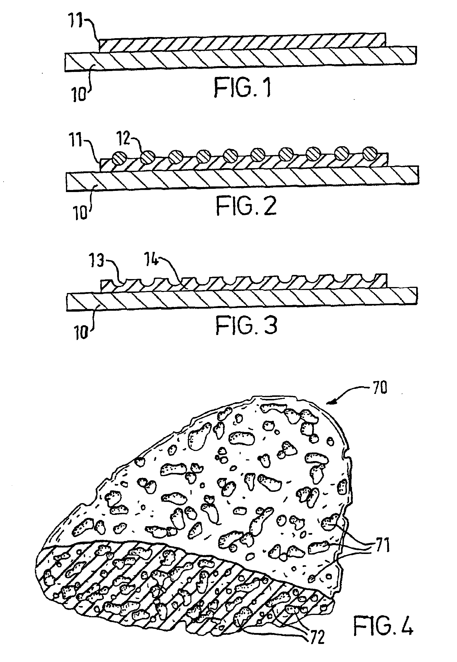
[0038]FIGS. 1, 2 and 3 show successive steps of the manufacturing process in accordance with the second aspect of the invention. In FIG. 1, the surface of a substrate 10 is coated with a layer of uncured silicone rubber precursor 11. In FIG. 2, a sacrificial filler 12, such as sodium chloride, is applied to the silicone rubber layer 11 whilst the latter is still tacky, the sodium chloride 12 becoming adhered to and partially embedded in the silicone rubber layer. Any excess sodium chloride 12 that is not adhered to the silicone rubber layer 11 is removed and the silicone rubber layer 12 is allowed to cure. Once the silicone rubber layer 11 has been cured, the sodium chloride 12 is dissolved in a solvent, such as water, leaving craters or micro-cupules 13 forming a textured surface structure 14 as shown in FIG. 3.

[0039]In FIG. 4, a porous silicone rubber article 70 has a textured exterior surface with craters 71 and pores 72 within the body of the silicone rubber article 70, forming ...


PUM

PropertyMeasurementUnit
Temperatureaaaaaaaaaa
Diameteraaaaaaaaaa
Particle sizeaaaaaaaaaa

Abstract

A method of making a silicone rubber having a structure adapted for growth of cells or living tissue, which comprises contacting a silicone rubber precursor with a biologically-acceptable sacrificial filler, curing the resultant mixture and removing the sacrificial filler to form a structured silicone rubber. The sacrificial filler is preferably an inorganic salt that has been ground, and the salt is selected from metal halides, metal carbonates and metal bicarbonates.

Description

BACKGROUND OF THE INVENTION[0001]The present invention relates to methods for manufacturing silicone rubber that is adapted to promote cell adhesion and growth, and, in particular, to methods for providing silicone rubber with a modified surface or structure for enhanced cell attachment. The resultant silicone rubber is well-suited to a variety of tissue culture and medical applications.[0002]Silicones surpass other elastomers in many performance categories because of their rigid silicon-oxygen chemical structure. The process of vulcanisation transforms this structure, allowing the silicon-oxygen polymer to become an elastic rubber. Silicone rubbers are stable throughout a temperature range of −46° C. to 232° C. They are odourless, tasteless and do not support bacterial growth. Silicone rubbers also do not stain or corrode with other materials. Most importantly, silicone rubbers are not physically or chemically degraded or altered by contact with body fluids, are not toxic or allerg...

Claims


Application Information

Patent Timeline
IPC IPC(8): A61L15/26A61L15/16A61L29/00A61L29/06A61L27/00A61L27/18C08J9/26C08J9/00C12M3/06A61F2/06A61F2/08A61F2/10A61F2/24A61F2/28C12M1/00A61F13/00A61K35/39A61K45/00A61K47/04A61K47/30A61L15/44A61P3/10A61P5/00A61P31/00A61P43/00C12M3/00C12N5/07C12N5/071
CPCA61L15/26A61L27/18C12M25/02C12M23/24C12M21/08A61L29/06C08J9/26C08L83/04C08J2383/04C08J2201/0442A61P31/00A61P43/00A61P5/00A61P3/10
Inventor FULLER, JESS PAULPEGG, DAVIDBIRD, ROBERT MCLEANCLIFFORD, TIMOTHY BURGESSCLAYSON, TONY
Owner CELLON
Why Eureka
Try Eureka