Liquid crystal projection device having a liquid crystal display element that includes an electroluminescent element

a projection device and liquid crystal technology, applied in the direction of projection devices, picture reproducers, instruments, etc., can solve the problems of difficult miniaturization of liquid crystal projection devices, difficult to make the diameter of fluorescent tubes etc. small, and achieve the effect of preventing the diminution of light amount, reducing voltage, and bright imag

Inactive Publication Date: 2005-05-31
SEIKO EPSON CORP
View PDF25 Cites 9 Cited by
  • Summary
  • Abstract
  • Description
  • Claims
  • Application Information

AI Technical Summary

Benefits of technology

[0012]In more detail, a first task of the present invention is to provide a miniature liquid-crystal projection device that can be driven with lower voltage than conventionally and in which a brighter image than conventionally is projected by preventing the diminution in the amount of light produced by divergence of the light, by employing an organic electroluminescent element having a resonator structure where light of good optical emission directionality is emitted.
[0013]A second task of the present invention is to provide a miniature liquid-crystal projection device in which a brighter image than conventionally is projected by increasing the amount of light that can be transmitted through a polarizing plate of the liquid crystal panel by using a polarization conversion element that can convert a polarization of the emitted light from the light source.
[0014]A third task of the present invention is to provide a miniature liquid-crystal projection device in which a brighter image than conventionally is projected, by increasing the amount of light that is transmitted through the polarizing plate of the liquid crystal panel by employing a polarization conversion element that functions in a specified wavelength band in projecting a color image.
[0015]A fourth task of the present invention is to provide a miniature liquid-crystal projection device in which a brighter image than conventionally is projected by increasing the amount of light that is transmitted through the aperture of a pixel and miniaturizing the device itself by employing a miniature luminescent element comprising a microlens array element that focuses the light on to pixel apertures of the liquid crystal panel.
[0016]A fifth task of the present invention is to provide a miniature liquid-crystal projection device in which a clear image is projected by raising the purity of the light that is projected and the brightness compared with conventional devices, by increasing the amount of light consisting of light of only a specified wavelength by employing miniature luminescent elements that emit light of only a specified wavelength, due to optical resonance, in projection of a color image.

Problems solved by technology

However, in the case of a light source employing a fluorescent tube or light-guide plate, it is difficult to make the diameter of the fluorescent tube etc. small.
There was therefore the problem that miniaturization of a liquid-crystal projection device was difficult, since the thickness of the light source itself could not be reduced below the diameter of the fluorescent tube.
Also, in the case of an electric discharge-type light source such as a metal halide lamp, the reflector of large aperture that was considered necessary to direct the light diverging from the light source parallel to the liquid crystal panel was a factor impeding miniaturization of the liquid-crystal projection device.
In particular in the case of a liquid-crystal projection device for color display, further miniaturization the liquid-crystal projection device was difficult owing to the need to provide liquid crystal display elements consisting of a light source as aforementioned and liquid crystal panel for each of the primary colors constituting the color image.
Also, Japanese Patent Laid-Open number Sho. 51-119243 does not clearly disclose a material constituting a luminescent layer of an electroluminescent element.
This therefore suffered from the problem that projection of a bright image could not be achieved since the light could not be effectively directed into the aperture of the projection lens.
A further problem was that the drive voltage required for an electroluminescent element using inorganic material is at least 100 volts, which is comparatively high.

Method used


Image

  • Liquid crystal projection device having a liquid crystal display element that includes an electroluminescent element
  • Liquid crystal projection device having a liquid crystal display element that includes an electroluminescent element
  • Liquid crystal projection device having a liquid crystal display element that includes an electroluminescent element

Examples


embodiment 1

Layout

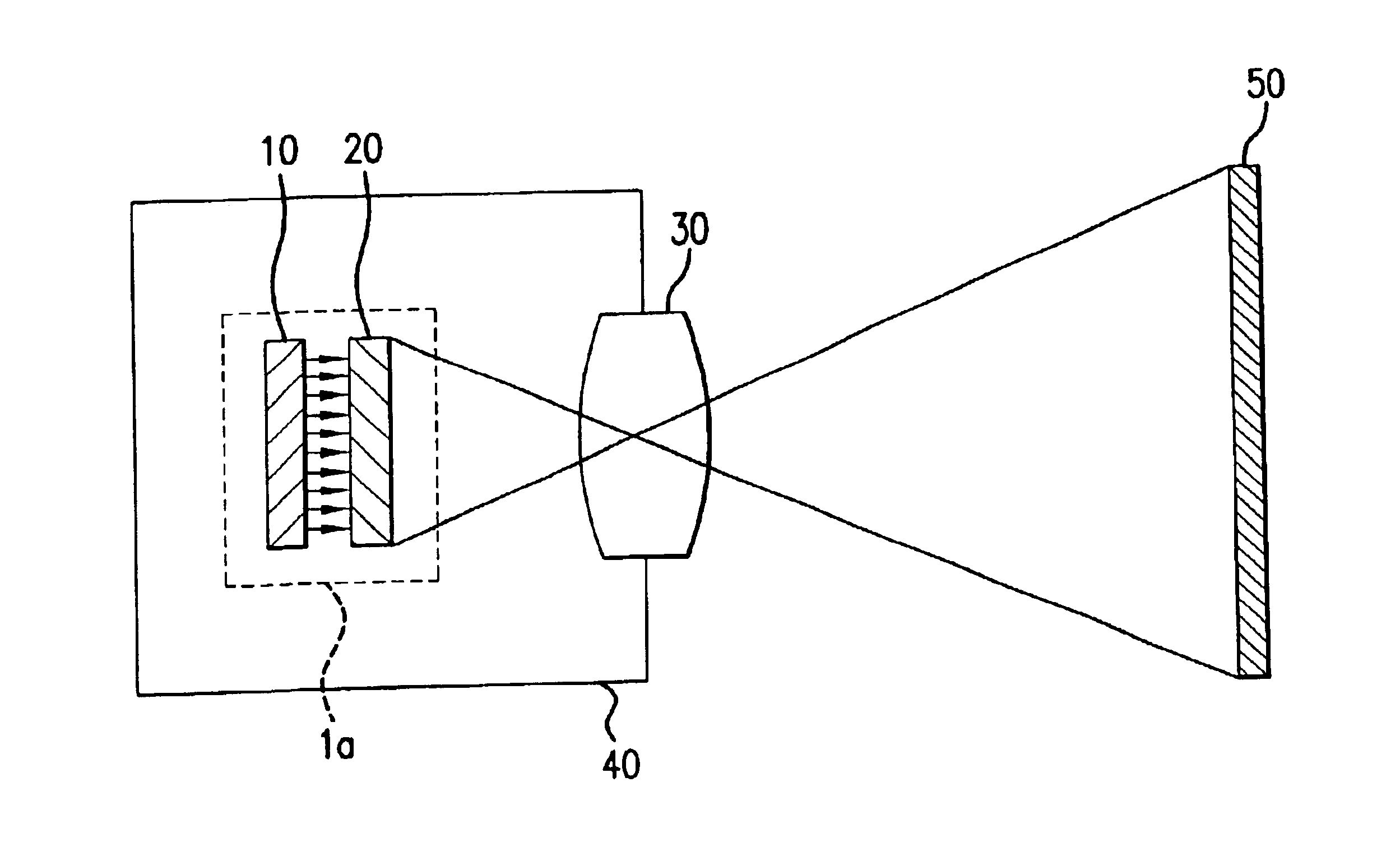
[0061]A liquid projection device according to the present invention, as shown in FIG. 1, includes a liquid crystal display element 1a, projection lens 30 and frame 40.

[0062]Projection lens 30 is constituted such that an image emitted from liquid crystal element 1a is imaged on a screen 50. Although only a single projection lens is shown in the Figure, this could of course be constituted by an assembly of a plurality of lenses. Specifically, the projection lens may be constructed so as to for example magnify the image emitted from liquid crystal display element 1a before it is formed on screen 50.

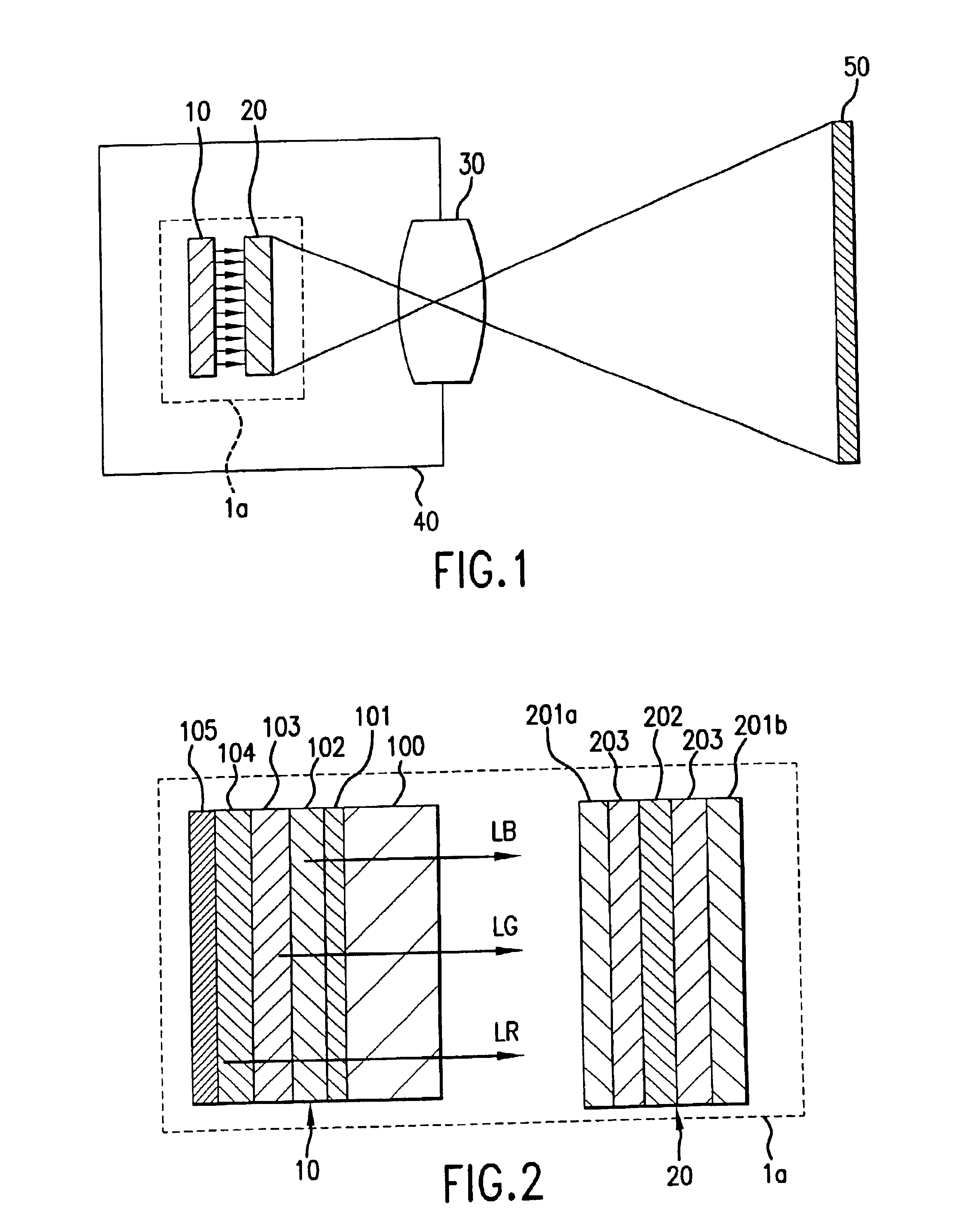
[0063]Frame 40 is constituted as a receptacle for accommodating the entire liquid-crystal projection device and is constituted such that the optical elements are suitably arranged therein. Its material is constituted such that it is unaffected by deformation etc. due to heat emission by liquid crystal display element 1a. Liquid crystal display element 1a, as shown in FIG. 2, includes a...

embodiment 2

[0089]Embodiment 2 of the present invention provides an organic electroluminescent element in which white light is obtained by luminescent layers different from those embodiment 1.

Construction

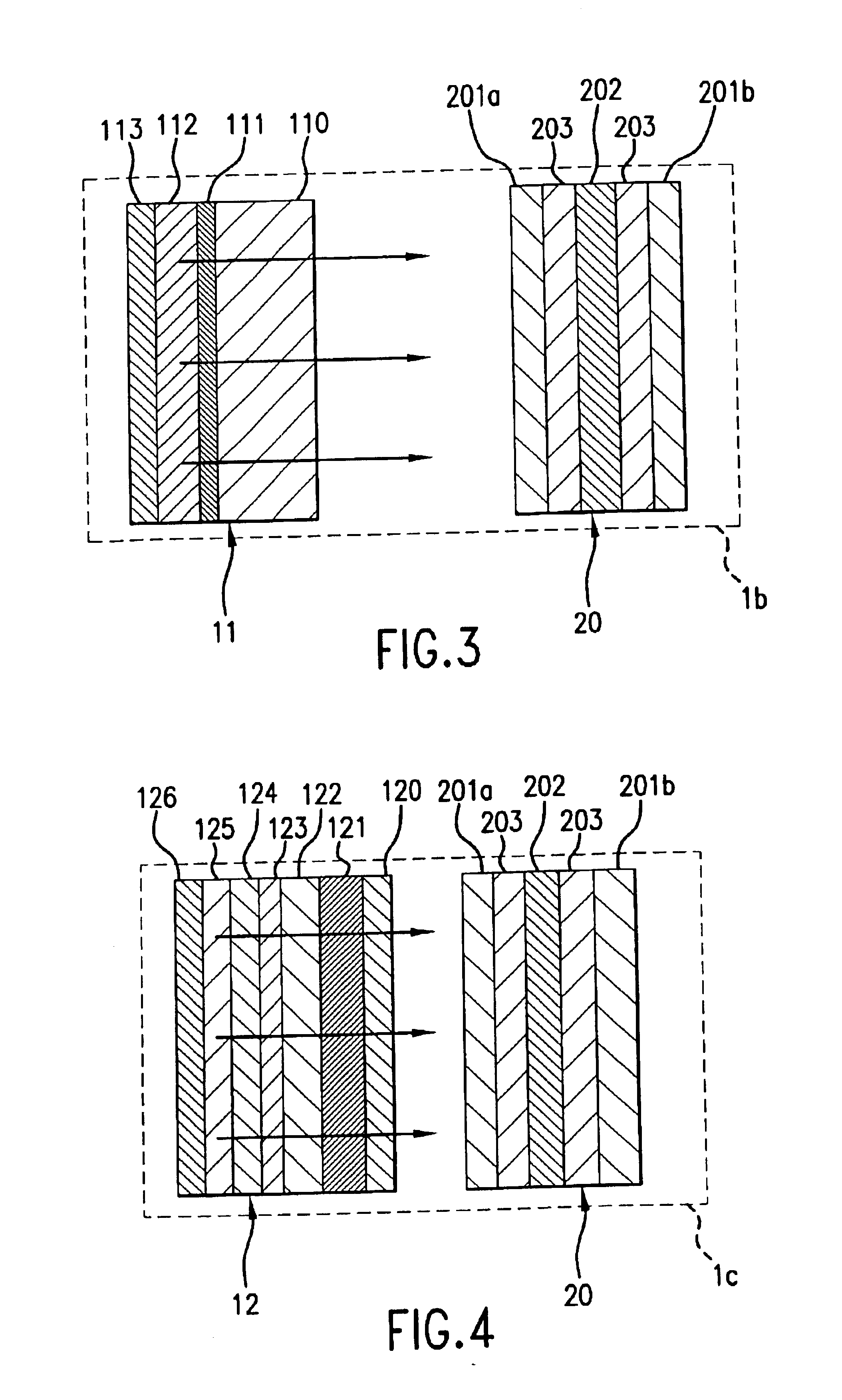
[0090]A liquid-crystal projection device according to embodiment 2 has the same construction (see FIG. 1) as embodiment 1 described above, except that liquid crystal display element 1b differs from embodiment 1 in that, as shown in FIG. 3, it comprises an organic electroluminescent element 11. The construction of liquid crystal panel 20 is identical with that of the first embodiment so as description thereof is omitted.

[0091]Organic electroluminescent element 11 is constituted by laminating a transparent electrode layer 111, white luminescent layer 112 and reflecting electrode layer 113 on the transparent substrate 110. Transparent substrate 110 is the same as transparent substrate 100 of embodiment 1, transparent electrode layer 111 is the same as transparent electrode layer 101 of embodiment ...

embodiment 3

[0097]Embodiment 3 of the present invention relates to an organic electroluminescent element whose directionality in the direction normal to the light-emitting face is strong due to an optical resonant structure and in which light of specified wavelength is emitted.

Construction

[0098]A liquid-crystal projection device according to embodiment 3 has the same construction as embodiment 1 (see FIG. 1) except for liquid crystal display element 1c. As shown in FIG. 4, liquid crystal display element 1c comprises an organic electroluminescent element 12 and a transparent liquid crystal panel 20. Liquid crystal panel 20 is identical with that of embodiment 1, so further description is omitted.

[0099]Organic electroluminescent element 12 is constituted by successive layers consisting of a transparent substrate 120, a dielectric mirror layer 121, a spacing adjustment layer 122, a transparent electrode layer 123, a positive hole transport layer 124, a luminescent layer 125, and reflecting electro...


PUM

PropertyMeasurementUnit
drive voltageaaaaaaaaaa
luminescence wavelengthaaaaaaaaaa
peak luminescence wavelengthaaaaaaaaaa

Abstract

A liquid-crystal projection device includes an organic electroluminescent element that is sandwiched by an organic thin-film layer between an electrode layer that reflects light and a transparent electrode layer that transmits light, and a transparent liquid crystal panel that controls passage of light emitted from the surface of the organic electroluminescent element and also includes a half-mirror layer arranged on the side where light is output from the transparent electrode layer. Some of the incoming light is reflected through the transparent electrode layer to another electrode layer and the rest of the light is transmitted the distance between the half-mirror layer. The electrode layer is set to the optical distance of resonance of the light.

Description

BACKGROUND OF THE INVENTION[0001]1. Field of the Invention[0002]The present invention relates to a liquid-crystal projection device i.e. what is known as a projector and in particular relates to improvements in the light source and peripheral optical system of a small-size liquid-crystal projection device.[0003]2. Description of the Related Art[0004]As the light sources employed is conventional liquid-crystal projection devices, light sources using a fluorescent tube or light-guide plate or electrical discharge-type light sources such as metal halide lamps have come to be employed.[0005]In particular, Japanese Patent Laid-Open number Sho. 51-119243 discloses a flat plate-shaped light source. This specification states that the flat plate-shaped light source employs electroluminescence i.e. electroluminescent elements.[0006]However, in the case of a light source employing a fluorescent tube or light-guide plate, it is difficult to make the diameter of the fluorescent tube etc. small. ...

Claims


Application Information

Patent Timeline
Patent Type & Authority Patents(United States)
IPC IPC(8): H04N9/31H01L51/52H01L51/50G02F1/1335G02F1/13357H05B33/22
CPCG02F1/133603H05B33/22H04N9/3105H04N9/3167H04N9/3197G02F1/133536G02F1/13362G02F2001/133543H01L51/5262G02F1/133543H10K59/8793H10K50/85
Inventor YOKOYAMA, OSAMUMIYASHITA, SATORUSHIMODA, TATSUYA
Owner SEIKO EPSON CORP
Why Eureka
Try Eureka