Projection optical system, exposure apparatus and exposure method

Inactive Publication Date: 2005-06-21
NIKON CORP
View PDF6 Cites 64 Cited by
  • Summary
  • Abstract
  • Description
  • Claims
  • Application Information

AI Technical Summary

Benefits of technology

[0012]It is an object of the present invention to provide a three-time image-forming catadioptric optical system having relatively high image-side numerical aperture and projection field, which is a projection optical system configured such that a clear aperture diameter of a concave reflective mirror is relatively small, mechanical stability in respect of vibrations is good, and it is easy to fabricate a fluorite lens arranged adjacently to the concave reflective mirror.
[0013]Moreover, it is another object of the present invention to provide a three-time image-forming catadioptric optical system having relatively high image-side numerical aperture and projection field, which is a projection optical system configured such that a distance between an object surface and an image surface is relatively small, mechanical stability in respect of vibrations is good, operativity is good when being mounted on an exposure apparatus, and an advantage is brought in terms of in

Problems solved by technology

However, if the wavelength of the illumination light is shortened, the light absorption will become remarkable, and types of glass materials (optical materials) that are durable enough to practical use will be limited.
Particularly, when the wavelength of the illumination light becomes 180 nm or less, materials practically usable are limited to fluorite only.
Consequently, in a dioptric (refractive) projection optical system, it becomes impossible to correct a chromatic aberration.
As described above, the dioptric projection optical system composed of a single glass material has limitations on an allowable chromatic aberration, and it is inevitable to make a band of a laser light source extremely narrow.
In this case, an increase in the cost of the laser light source as well as a decrease in the output thereof cannot be avoided.
However, in the conventional projection optical system disclosed in International Publication WO01/65296, a clear aperture diameter of a concave reflective mirror in the catadioptric second image-forming optical system configuring a protruding portion thereof is relatively large, and therefore mechanical stability in respect of vibrations is apt to be damaged.
Moreover, a clear aperture diameter of a lens arranged adjacently to the concave reflective mirror is also relatively enlarged, and therefore it is not easy to procure and pro

Method used


Image

  • Projection optical system, exposure apparatus and exposure method
  • Projection optical system, exposure apparatus and exposure method
  • Projection optical system, exposure apparatus and exposure method

Examples


Example

[First Embodiment]

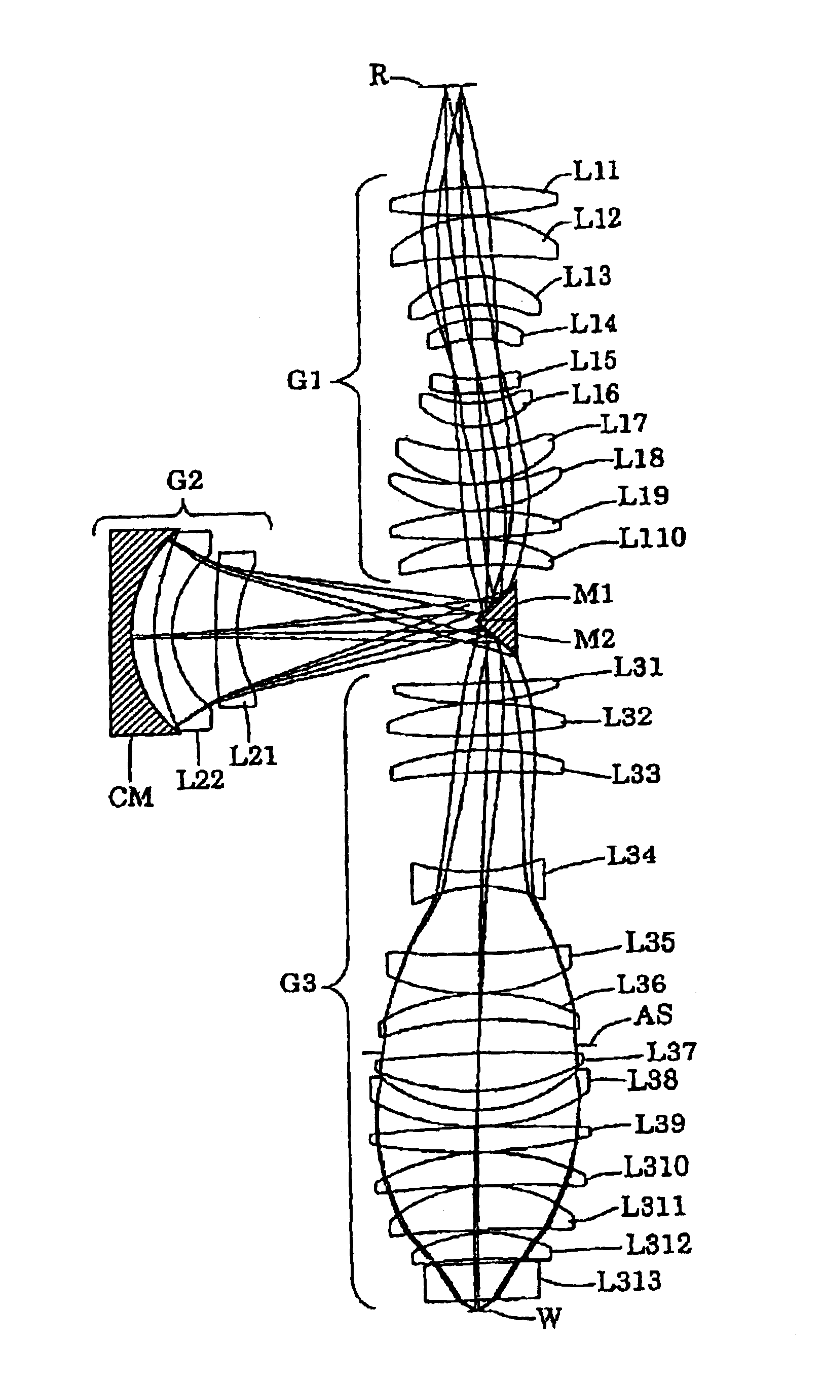
[0083]FIG. 4 is a diagram illustrating a constitution of lenses of a projection optical system according to a first embodiment of the present embodiments. Referring to FIG. 4, in the projection optical system PL according to the first embodiment, the first image-forming optical system is composed of, in order from the reticle side, the biconvex lens L11, the positive meniscus lens L12 orienting its aspheric concave surface to the wafer side, the positive meniscus lens L13 orienting its convex surface to the reticle side, the positive meniscus lens L14 orienting its convex surface to the reticle side, the negative meniscus lens L15 orienting its concave surface to the reticle side, the positive meniscus lens L16 orienting its concave surface to the reticle side, the positive meniscus lens L17 orienting its aspheric concave surface to the reticle side, the positive meniscus lens L18 orienting its concave surface to the reticle side, the biconvex lens L19, and the pos...

Example

[Second Embodiment]

[0091]FIG. 6 is a diagram illustrating a configuration of lenses of a projection optical system according to a second embodiment of the present embodiments. Referring to FIG. 6, in the projection optical system PL according to the second embodiment, the first image-forming optical system G1 is composed of, in order from the reticle side, the biconvex lens L11, the positive meniscus lens L12 orienting its aspheric concave surface to the wafer side, the positive meniscus lens L13 orienting its convex surface to the reticle side, the positive meniscus lens L14 orienting its convex surface to the reticle side, the negative meniscus lens L15 orienting its concave surface to the reticle side, the positive meniscus lens L16 orienting its concave surface to the reticle side, the positive meniscus lens L17 orienting its aspheric concave surface to the reticle side, the positive meniscus lens L18 orienting its concave surface to the reticle side, the positive meniscus lens ...


PUM


Abstract

Disclosed is a projection optical system having relatively large image-side numerical aperture and projection field and being excellent in mechanical stability in respect of vibrations, and the like. The projection optical system includes a first image-forming optical system for forming a first intermediate image of a first surface (R), a second image-forming optical system having a concave reflective mirror and for forming a second intermediate image based on a radiation beam from the first intermediate image, and a third image-forming optical system for forming a final image on a second surface based on a radiation beam from the second intermediate image. Then, predetermined conditional expressions are satisfied with regard to a clear aperture diameter of the concave reflective mirror, a distance (L) between the first surface and the second surface, and a distance (H) between the concave reflective mirror and a reference optical axis.

Description

BACKGROUND OF THE INVENTION[0001]1. Field of the Invention[0002]The present invention relates to a projection optical system, an exposure apparatus and an exposure method. More particularly, the present invention relates to a high-resolution catadioptric projection optical system suitable for a projection exposure apparatus used when semiconductor devices and liquid crystal display devices are fabricated in a photolithography step.[0003]2. Related Background of the Invention[0004]In a photolithography step for fabricating semiconductor devices or the like, a projection exposure apparatus for exposing a pattern image of a photomask or a reticle (hereinafter, generically referred to as “reticle”), through a projection optical system, on a wafer (or a glass plate) which is coated with photoresist and the like is used. Then, as a scale of integration of the semiconductor devices or the like is improved, resolving power (resolution) required for the projection optical system of the proje...

Claims


Application Information

Patent Timeline
IPC IPC(8): G03F7/20G03B21/00G02B17/08G02B13/18G02B27/18H01L21/027
CPCG03F7/70275G03B21/00G03B21/006H01L21/027
Inventor OMURA, YASUHIRO
Owner NIKON CORP
Why Eureka
Try Eureka