

Alloy composition and method for low temperature fluxless brazing
a technology of fluxless brazing and alloy composition, which is applied in the direction of metal-working apparatus, non-electric welding apparatus, metallic material coating process, etc., can solve the problems of difficult control, added cost, and difficulty in controlling the as-brazed zinc composition in the aluminum structure being brazed
- Summary
- Abstract
- Description
- Claims
- Application Information
AI Technical Summary
Benefits of technology
Problems solved by technology
Method used
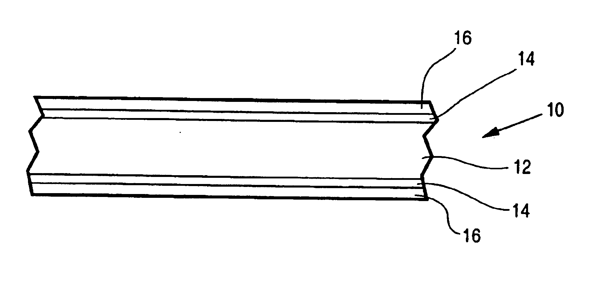
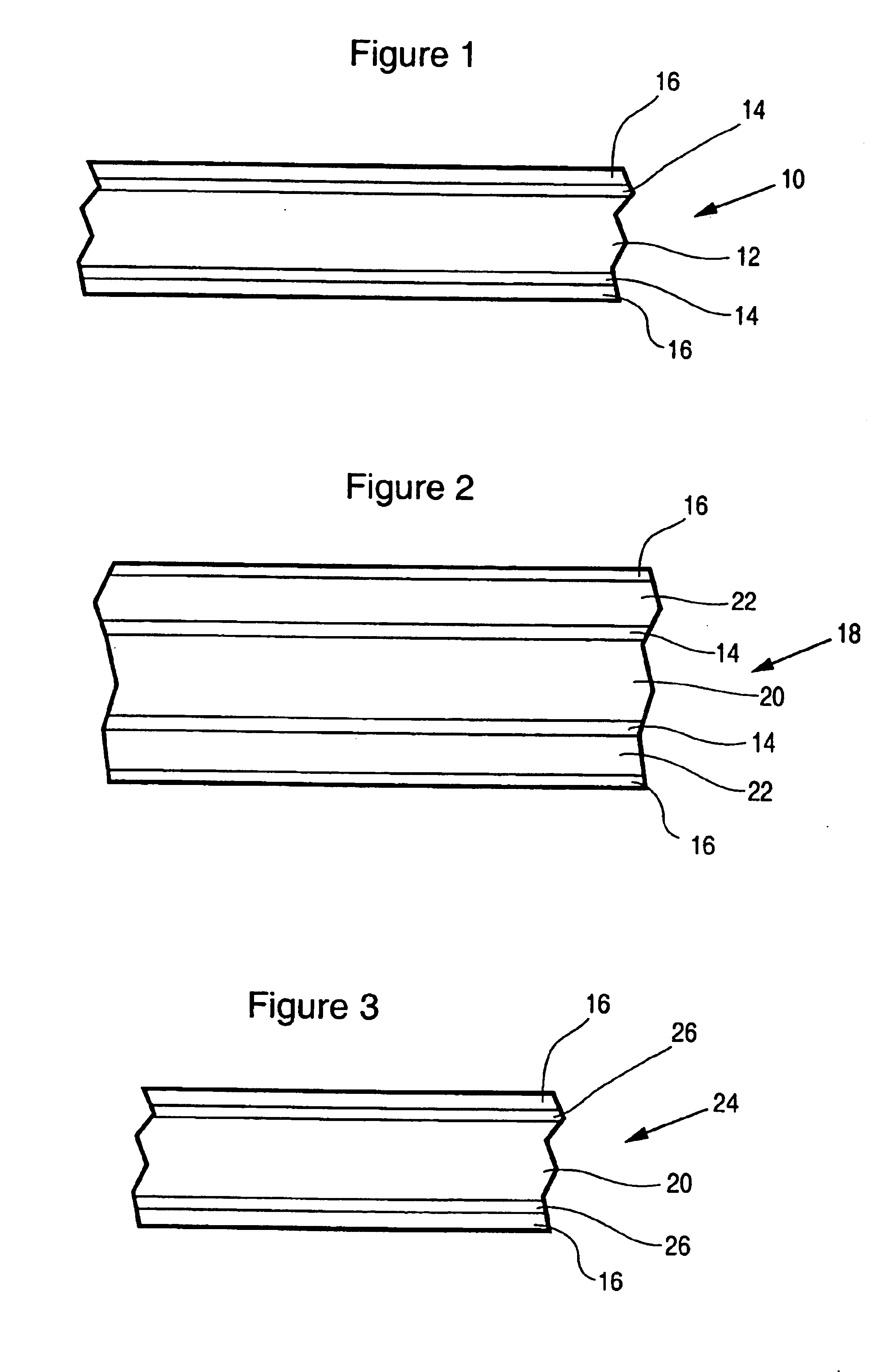
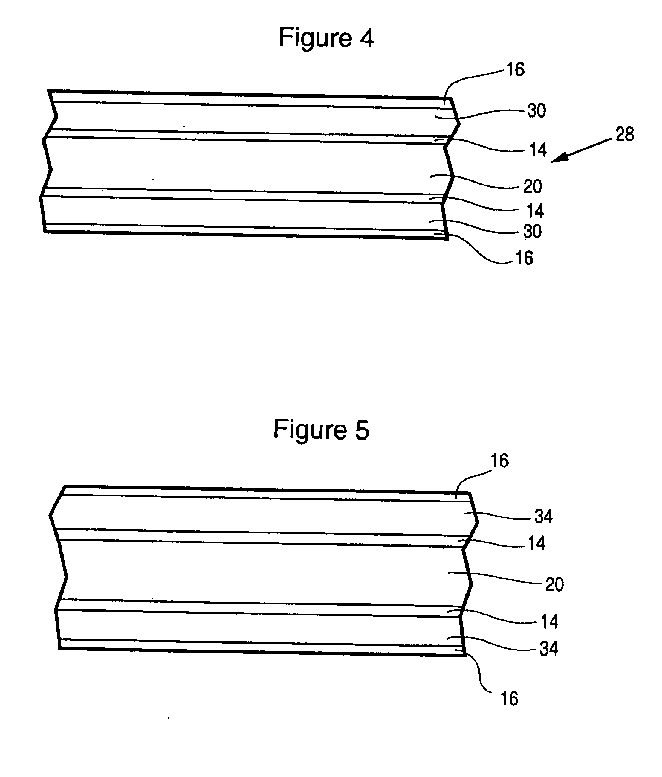
Image

Examples
examples and tables
Example 1
[0078]Table 1 indicates how various combinations of braze filler metal can reduce melting temperatures as aluminum concentrations decrease and zinc concentrations increase, with a sharp temperature decrease occurring at the eutectic at 4% aluminum—96% zinc.
[0079]
TABLE IAl (%)Zn (%)Si (%)Pb (%)Ta (%)Bi (%)° F.0.0 100.0 ————7864.096.0————7203.595.0—1.5——75213.085.31.2—0.5—80020.576.02.0——1.585029.066.03.02.0——88538.257.04.8———91046.547.56.0———95054.838.07.2———98563.128.58.4———101588.2—11.8 ———1100
[0080]The alloys shown in Table 1 were prepared experimentally by casting, rolled into sheet, and then used to determine a successful melting range and also wetting and spreading characteristics. These experiments showed that the introduction of an increasing percentage of zinc to the traditional eutectic aluminum-silicon filler alloy, reduced the melting temperature of the new brazing alloy. The wetting and spreading tests also proved that the zinc-aluminum-silicon systems according...
example 2
[0082]Several tensile strength measurements were made with brazed lap specimens, using zinc alone and nickel-lead plated zinc as filler materials (Table 2) to bond type 3003 aluminum to 3003 aluminum.
[0083]With respect to the various tests, nos. 1 through 5 uses aluminum type 3003 and zinc foil that is 0.38 mm. thick and nos. 6 through 11 utilize zinc foil which is 0.10 mm. thick. The braze tests were run with type 3003 aluminum as a lap joint with a small sheet of zinc placed between the 3003 aluminum pieces. As shown in table 2, the electroplated nickel-lead on zinc greatly improved the braze quality and strength and made it possible to lower the braze temperature to 900° F.
[0084]
TABLE 2FillerZinc ThicknessBrazeBraze Temp.BrazeTensileNo.Material(mm)Promoter(° F.)QualityStrength (lb)1Zinc0.38—1120Good4552Zinc0.38Ni—Pb950Good4903Zinc0.38—950Poor904Zinc0.38Ni—Pb900Good5485Zinc0.38—900Poor806Zinc0.10—900No Braze—7Zinc0.10Ni—Pb900Good5368Zinc0.10—950No Braze—9Zinc0.10—1000No Braze—10Zi...
example 3
[0085]A second group of tests were conducted as in Example 2 but with a shorter lap joint in the order of 0.25 inches using 3003 aluminum specimens. For all tests, a small piece of zinc metal was placed between the aluminum specimens and, as shown in table 3, the braze temperature was lowered to 800° F. when nickel-lead was electroplated on the zinc spacer.
[0086]
TABLE 3FillerBrazeBraze Temp.BrazeTensileNo.MaterialPromoter(° F.)QualityStrength (lb)1ZincNi—Pb850Good6482ZincNi—Pb800Good5803Zinc—1100Poor1364ZincNi—Pb900Good5165Zinc—1000No Braze—
PUM
| Property | Measurement | Unit |
|---|---|---|
| Temperature | aaaaa | aaaaa |
| Temperature | aaaaa | aaaaa |
| Temperature | aaaaa | aaaaa |
Abstract
Description
Claims
Application Information