High-efficiency fuel cell power system with power generating expander

a fuel cell and power system technology, applied in the direction of cell components, fused electrolyte fuel cells, cell component details, etc., can solve the problems of waste heat generated in conventional low-temperature fuel cells, is notoriously difficult to recapture in a way that produces additional useful power, and the heat rejection temperature of low-temperature fuel cells is much too low to recover energy, so as to improve the overall system efficiency and improve efficiency. , the effect of improving efficiency

Inactive Publication Date: 2005-07-12
NUVERA FUEL CELLS
View PDF68 Cites 11 Cited by
  • Summary
  • Abstract
  • Description
  • Claims
  • Application Information

AI Technical Summary

Benefits of technology

[0006]In general, the present invention relates to fuel cell-based power systems, including integrated fuel reformer / fuel cell systems and “pure” hydrogen-based fuel cell power systems, having improved efficiency. In one aspect, the fuel cell systems of the present invention advantageously utilize low-temperature waste heat of the fuel cell to generate additional power, thus permitting improvements in overall system efficiency. The system comprises a fuel cell having an anode and a cathode; a source of hydrogen gas which is provided to the anode of the fuel cell; and a compressor which creates a pressurized air stream that is provided to the cathode of the fuel cell. The pressurized air stream of the cathode and the hydrogen gas of the anode react at the fuel cell to produce an electrical power output and waste heat. The system further comprises a cooling liquid (e.g. water), which removes low-temperature waste heat from the fuel cell. The cooling liquid, warmed directly or indirectly by waste heat from the power system, is evaporated into a pressurized air stream, which may be the oxidant air stream to, from, or within the fuel cell cathode, to produce a pressurized steam-laden air stream. The steam-laden air stream is then fed, along with a fuel, to a burner, where it is burned to generate a high-temperature steam-laden exhaust stream. The steam-laden exhaust stream is used to drive an expander, such as a turbine, to provide a power output. The power output from the expander is generally in excess of the power used to compress the air, and the expander power can be used, via a power take-off, to drive auxiliary components of the system, such as a compressor or pump, and / or to supplement the system power output from the fuel cell, such as by driving an electrical generator.
[0015]The pure hydrogen fuel cell power system of the present invention advantageously uses a pressurized air stream as the cathode oxidant, which results in increased fuel cell power output, or smaller fuel cell size for a given output power. Moreover, this added performance due to higher pressure is “free” in terms of parasitic load, as the power generated by the expansion of the steam-laden exhaust more than compensates for the power required to pressurize the air. Of course, the addition of the burner tends to decrease system efficiency, as typically some excess fuel is consumed by the burner. However, this is more than offset by the energy recaptured from the waste heat of the system via the evaporation of water into the pressurized cathode air stream. The expansion of the steam-laden exhaust creates net energy, in excess of the cost of compressing the air and any excess fuel used in the burner, and therefore overall system efficiency is improved. The resulting system is also typically very flexible and can respond rapidly to transients.
[0016]According to yet another aspect, the present invention comprises a fuel cell power system and a method of operation of such a system, the system comprising a fuel cell with an anode and a cathode, a compressor for creating a pressurized air stream, the air stream being provided to the cathode of the fuel cell for generating an electrical power output, a cooling liquid in fluid communication with the pressurized air stream, at least a portion of the cooling liquid being heated by waste heat from the power system and evaporating into the pressurized air stream to produce a pressurized mixture of air and steam, a burner for combusting fuel with the pressurized steam / air mixture to produce a high-temperature exhaust steam-containing exhaust stream, and an expander that is driven by the exhaust to produce a power output. Additionally, the system comprises a condensing apparatus, such as a radiator, for recovering at least a portion of the evaporated liquid from the expanded burner exhaust prior to discharge of the exhaust from the system. In certain embodiments, the system additionally comprises an apparatus for applying a backpressure to the burner exhaust to facilitate recovery of evaporated liquid from the burner exhaust. The backpressure can be selectively applied to raise the dew point of the exhaust stream, and thus make the liquid in the exhaust more easily recoverable, particularly when the system is operated at high ambient temperatures. This technique is applicable to “pure” hydrogen fuel cells, and to “direct” fuel cells that convert fuel to hydrogen directly in the fuel cell, as well as to “hybrid” fuel cell power systems which include an integrated fuel reformer sub-system.

Problems solved by technology

The waste heat generated in conventional low-temperature fuel cells, such as the well-known “PEM” cells (polymer electrolyte membrane or proton exchange membrane cells; sometimes called solid polymer electrolyte membrane cells), is notoriously difficult to recapture in a way that produces additional useful power.
The heat rejection temperatures for these low-temperature fuel cells are much too low to recover energy via conventional means, such as steam turbine or other Rankine-type “bottoming cycles.” Consequently, the waste heat of such low-temperature fuel cells is simply discharged to the environment through a closed-loop radiator or other means.

Method used


Image

  • High-efficiency fuel cell power system with power generating expander
  • High-efficiency fuel cell power system with power generating expander
  • High-efficiency fuel cell power system with power generating expander

Examples


first embodiment

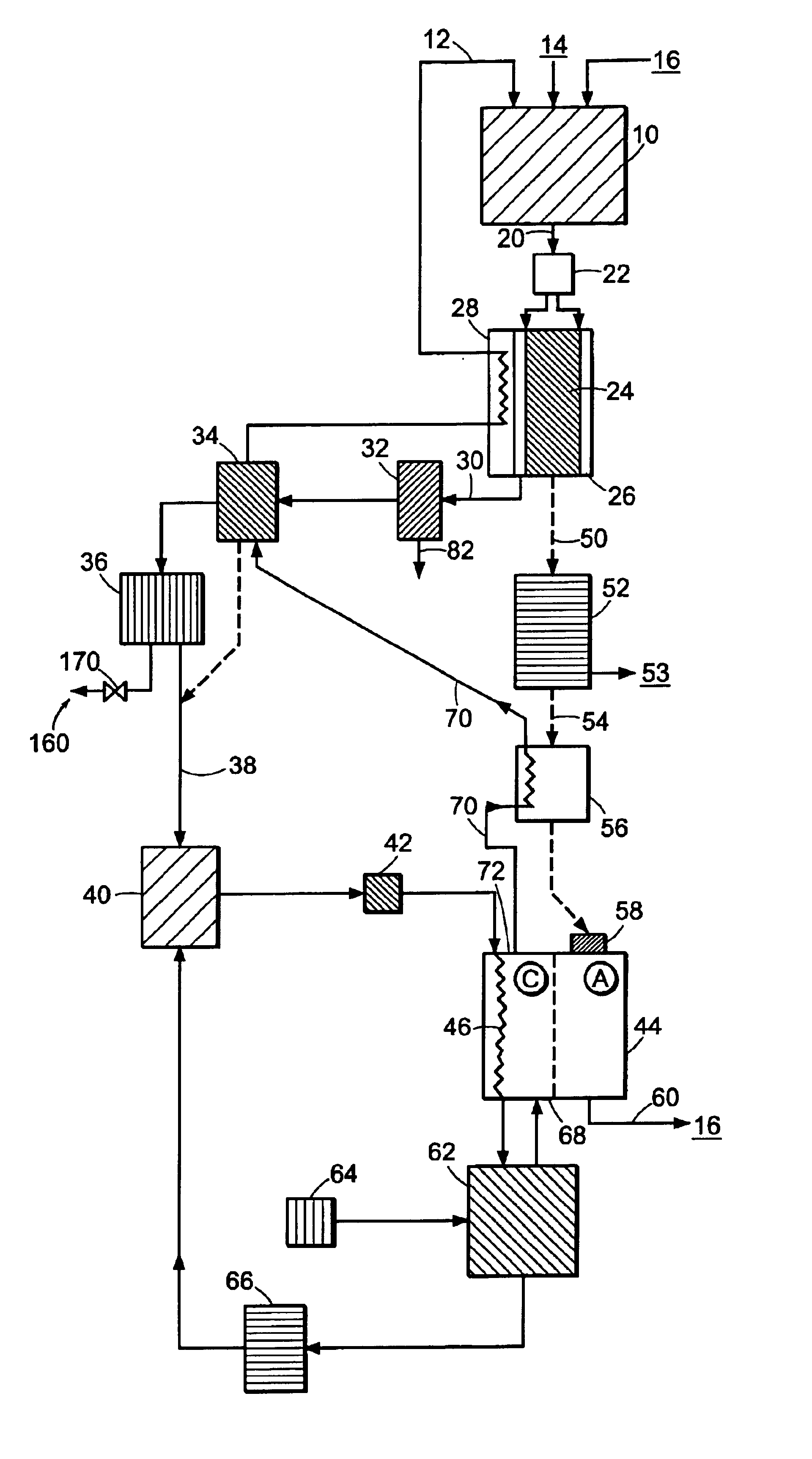
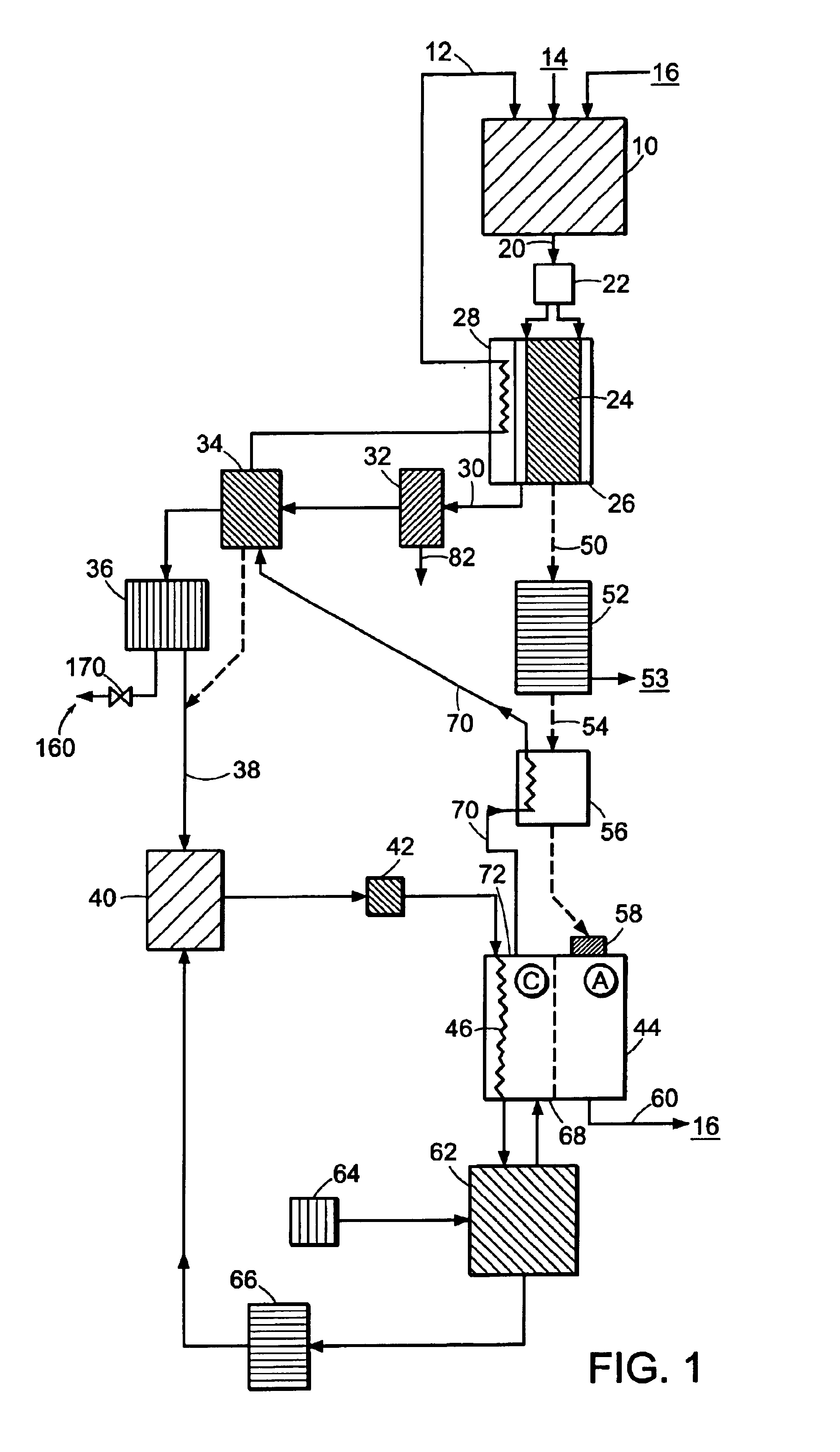
[0026]One embodiment of an integrated fuel reformer / fuel cell power system of the invention is schematically illustrated in FIG. 1. A burner 10 receives feeds of air / steam 12, fuel 14 and preferably recycled fuel cell anode exhaust 16, and combusts them to create a hot exhaust 20. Any or all of the burner inputs (air, fuel, and recycled fuel cell exhaust) may be preheated by heat exchange in any suitable zone containing heat to be removed. In particular, the air / steam flow 12 is typically preheated, as described below.

[0027]The exhaust transfers its heat to a reformer 24 by contact of the exhaust with the walls of the reformer and / or by other types of heat exchanger, such as the shell-type exchanger 26 that is schematically illustrated. The reformer has inputs of fuel, steam, and optionally oxygen or air, depending on the exact design of the system (these inputs are not labeled for clarity). The heat-exchanger 26 optionally may have additional heat exchange provisions 28 for superhe...

second embodiment

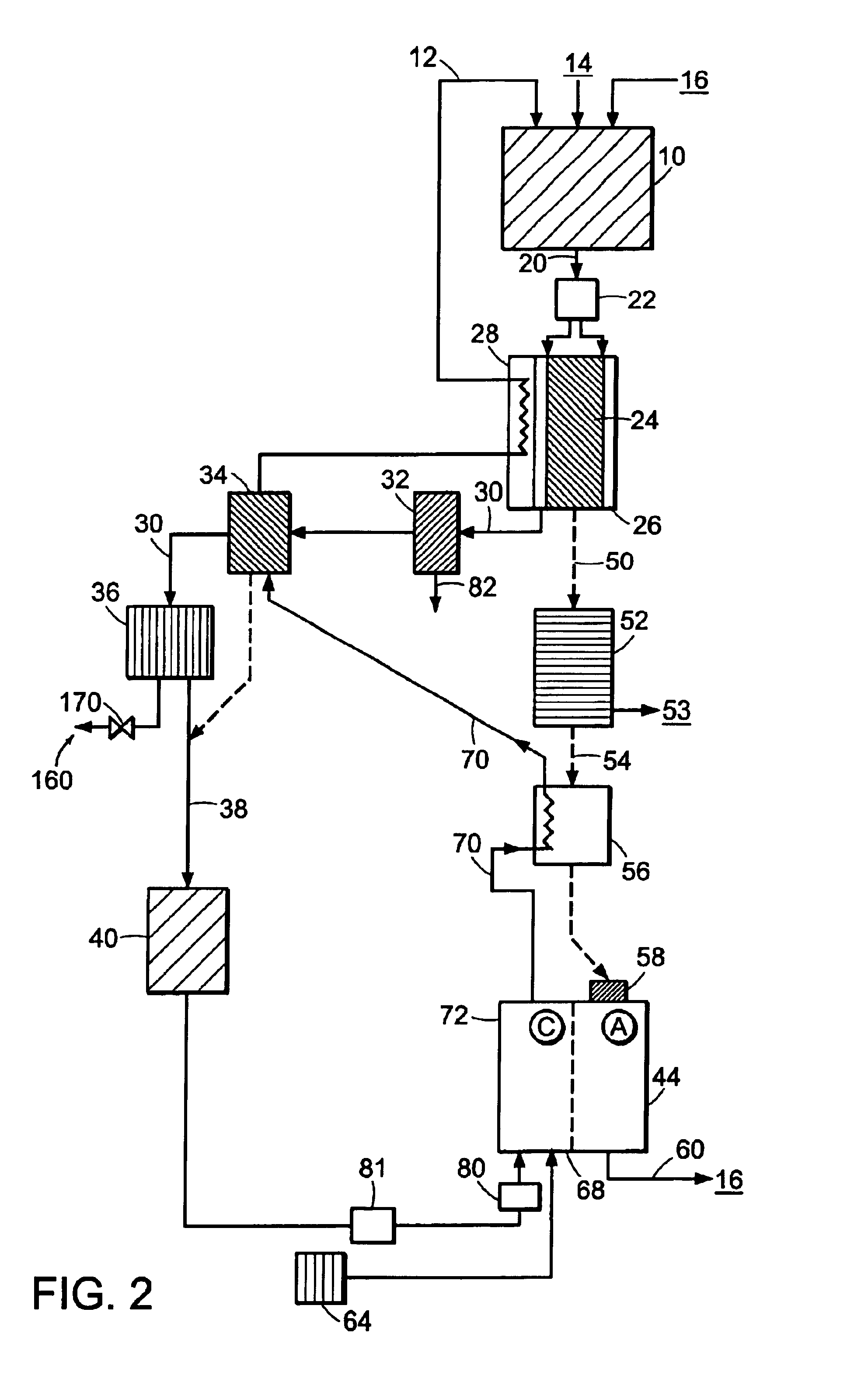
[0039]A second exemplary embodiment of an integrated fuel reformer / fuel cell power system of the invention is shown in FIG. 2. This embodiment is similar to the embodiment shown in FIG. 1, except that here, the pressurized air / steam mixture is produced (at least in part) by direct injection of water into the fuel cell stack. The injected water thus achieves the dual functions of cathode air humidification, as well as cooling of the fuel cell. Direct water injection for fuel cell humidification / cooling is described in greater detail in commonly-owned International Application No. PCT / EP00 / 03171 (Publication No. WO 00 / 63992), the entire teachings of which are incorporated herein by reference. Direct water injection can be used as a supplement to, or even a replacement of, the previously-described fuel cell cooling loop. As shown in FIG. 2, the saturator / mixer 62 (from FIG. 1) has been replaced by an injector 80 and pump 81. Water is supplied to injector 80 in a desired amount by pump ...

third embodiment

[0049]The “joint cycle” can also be applied to systems that do not contain a reformer. By addition of a burner to combust waste fuel from the anode, and by use of the waste heat of the fuel cell to evaporate water into compressed air, a steam-laden exhaust stream can be provided to an expander, thereby allowing the capture of the waste heat as mechanical energy.

[0050]An example of a non-hybridized “pure” hydrogen fuel cell power system of the invention is illustrated schematically in FIG. 3. A fuel cell stack 110, such as a PEM stack, has an anode compartment 112, a cathode compartment 114, and a cooling apparatus 116. The anode 112 is fed with hydrogen from a pressurized source 120, such as a storage tank. The cathode 114 is supplied with an oxygen-containing gas, which preferably comprises a pressurized air / steam mixture. Electrochemical reactions between the hydrogen and oxygen-containing reactants of the fuel cell produce an electrical power output.

[0051]In addition to useful el...


PUM

PropertyMeasurementUnit
operating temperatureaaaaaaaaaa
temperaturesaaaaaaaaaa

Abstract

A hydrogen fuel cell power system having improved efficiency comprises a fuel cell, a source of hydrogen gas, a compressor for creating a pressurized air stream, and a liquid supply which is heated by waste heat form the power system and evaporates into the pressurized air stream to produce a pressurized air and steam mixture. The pressurized air / steam mixture, which is preferably used as the oxidant in the fuel cell, is combusted with fuel in a burner to produce a high-temperature steam-laden exhaust stream. The high-temperature steam-laden exhaust stream drives an expander to produce a power output, and a power take-off from the expander uses the expander power to, for instance, drive an electrical generator, or drive other system components. The evaporation of liquid can take place external to the fuel cell, or can take place directly within the fuel cell, preferably using a cooling liquid that is directly injected into the fuel cell. The fuel cell power system advantageously uses the low-temperature waste heat of the fuel cell to evaporate liquid into the pressurized air, resulting in a steam / air mixture having a relatively large expansion potential.The systems and related methods of the invention are applicable to a wide range of fuel cell power systems, including a “pure” or “non-hybrid” fuel cell power system, powered by hydrogen from either an external source, such as a hydrogen storage tank, or from “direct” reforming of a fuel at the anode. The invention is also applicable to integrated or “hybridized” fuel cell power systems which contain a local fuel reformer. In these systems, the fuel cell is powered by hydrogen-containing reformate generated by the reformer.

Description

RELATED APPLICATIONS[0001]This application is a continuation-in-part of U.S. application Ser. No. 09 / 870,412, filed May 30, 2001, which claims the benefit of U.S. Provisional Application No. 60 / 208,355, filed May 31, 2000. This application is also a continuation-in-part of U.S. application Ser. No. 10 / 309,779, filed Dec. 4, 2002 now U.S. Pat. No. 6,817,182, which claims the benefit of U.S. Provisional Application No. 60 / 338,637, filed Dec. 5, 2001. The entire teachings of the above applications are incorporated herein by reference.BACKGROUND OF THE INVENTION[0002]A fuel cell is an electrochemical device that converts the chemical energy of a reaction into electrical energy. A fuel cell consists of an anode and a cathode separated by an electrolyte layer. In operation, a reactant, typically hydrogen gas, is fed to the anode, and an oxidant, typically air or other oxygen-containing gas, is fed to the cathode. The electrochemical reactions which take place at the fuel cell produce an e...

Claims


Application Information

Patent Timeline
Patent Type & Authority Patents(United States)
IPC IPC(8): H01M2/00H01M2/02H01M8/12H01M8/04H01M8/06H01MH01M8/00H01M8/10H01M8/14H01M8/18
CPCH01M8/04022H01M8/04089H01M8/04111H01M8/04126H01M2008/1095H01M2250/402H01M2250/407Y02B90/12Y02E60/563Y02E60/50Y02B90/10
Inventor CLAWSON, LAWRENCE G.O'BRIEN, CHRISTOPHER J.HAGAN, MARK R.
Owner NUVERA FUEL CELLS
Why Eureka
Try Eureka