

Phase interpolation receiver for angle modulated RF signals
a phase interpolation and receiver technology, applied in phase-modulated carrier systems, multi-frequency-changing modulation transference, amplitude demodulation, etc., can solve the problem of complex distributed agcs, limit the dynamic range of channel filters and fm discriminators, and the known zero-if receivers for pwt with /4 dqpsk modulation are even more complicated
- Summary
- Abstract
- Description
- Claims
- Application Information
AI Technical Summary
Benefits of technology
Problems solved by technology
Method used
Image

Examples
first embodiment
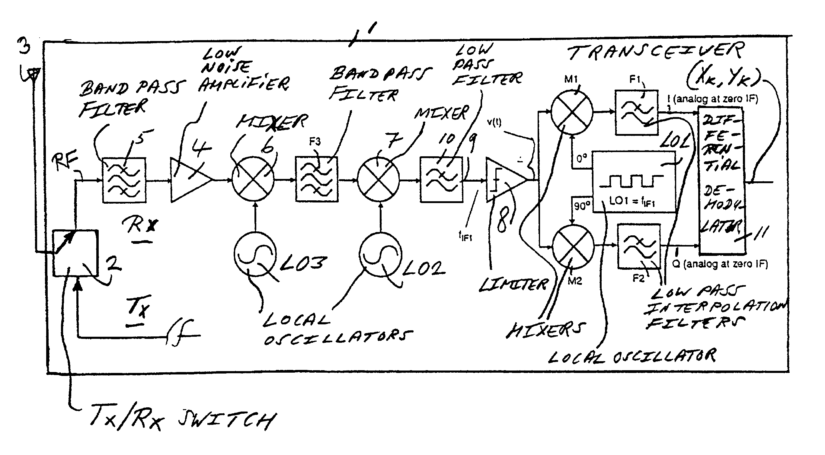
[0044]FIG. 1 is a block diagram of a transceiver 1 with a receiver Rx according to the present invention. The receiver Rx is a double super heterodyne receiver with three-step down-conversion from RF to zero-IF or base band. The transceiver, a DECT or a PWT receiver, for instance, comprises a Tx / Rx switch 2 for coupling the receiver Rx to an antenna 3. The Tx / Rx switch 2 is further coupled to a transmit branch Tx that is not shown in detail here. The receiver Rx comprises a low noise RF amplifier 4 that is coupled to the Tx / Rx switch 2 through an RF band pass filter 5. The RF band pass filter 5 receives an angle modulated radio frequency signal RF at the antenna 3. The low noise amplifier 4 is coupled to first down-conversion means, a mixer 6, and a mixer 7, the mixer 6 being coupled to a local oscillator LO3, and the mixer 7 being coupled to a local oscillator LO2. The mixer 6 is coupled to the mixer 7 through a band pass filter F3. The receiver Rx comprises a limiter 8 for a gener...
second embodiment
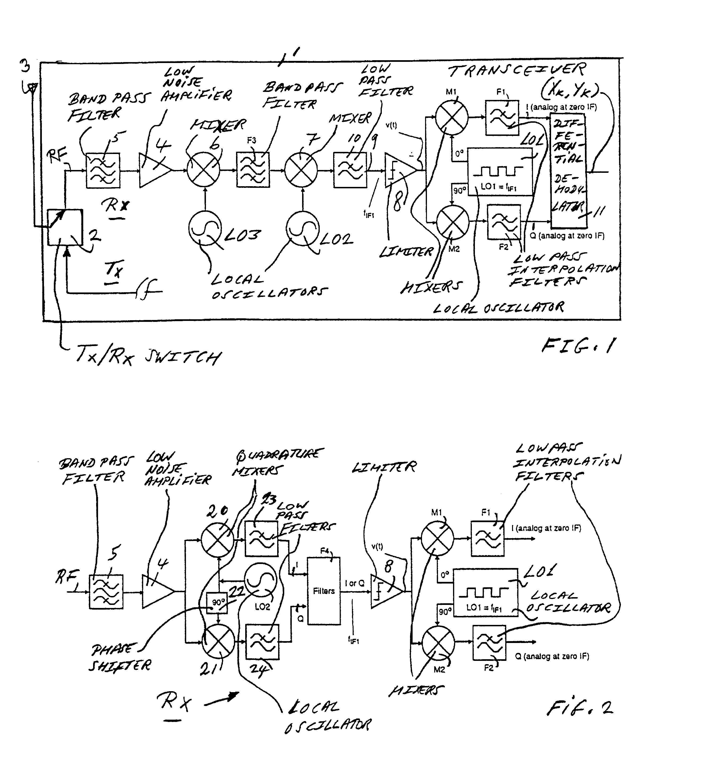
[0047]FIG. 2 is a block diagram of a receiver according to the present invention. In this embodiment, the receiver Rx is a low-IF receiver with two-step quadrature down-conversion from RF to zero-IF or base band. The receiver Rx comprises a quadrature down-conversion means, quadrature mixers 20 and 21. The mixers 20 and 21 are coupled to the local oscillator LO2, directly and through 90° phase shifter 22, respectively. The mixers 20 and 21 are further coupled to the limiter 8 through a cascade of low pass filters 23 and 24, and poly-phase filters F4.
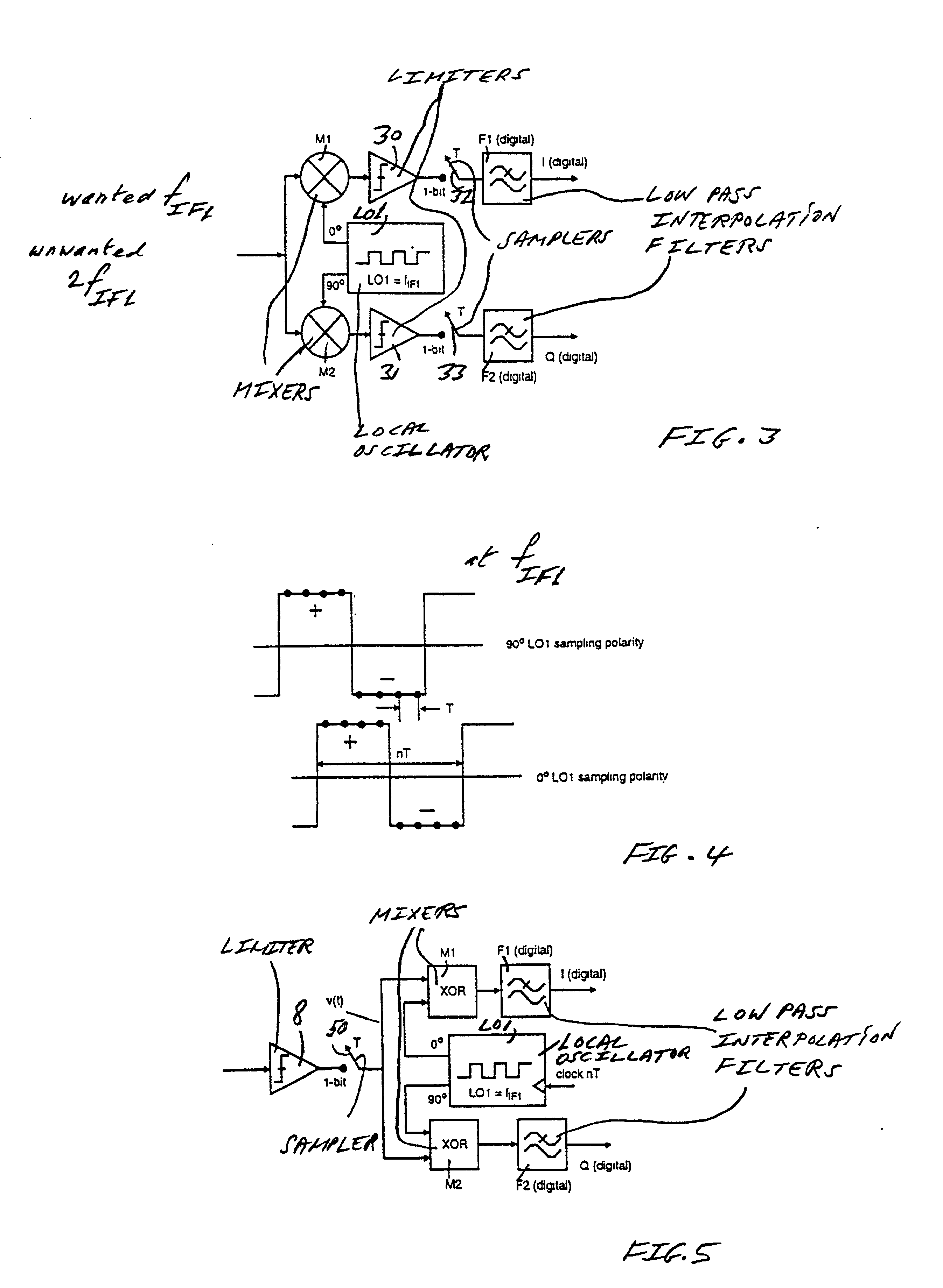
[0048]In the double superhet receiver Rx of FIG. 1, and in the poly phase receiver Rx of FIG. 2, the noise spreading signal is a very low unwanted 2fIF1 frequency term at the output of the mixers M1 and M2. The hard-limited IF signal is mixed with a square wave LO. This is equivalent to mixing a non-limited IF signal with a sinusoidal LO, and then limiting the signal at the mixer output, as shown in FIG. 3, in which limiters 30 and 31 ar...
PUM
 Abstract
Description
Claims
Application Information