Multizone carrier with process monitoring system for chemical-mechanical planarization tool

a multi-zone carrier and process monitoring technology, applied in the field of semiconductor manufacturing, can solve the problems of poor optical resolution of subsequent photolithography processing steps, both faces of the wafer to be extremely rough, and poor optical resolution of non-planar surfaces, etc., to achieve the effect of preventing the printing of high-density lines and poor optical resolution

Inactive Publication Date: 2005-08-02
NOVELLUS SYSTEMS
View PDF23 Cites 25 Cited by
  • Summary
  • Abstract
  • Description
  • Claims
  • Application Information

AI Technical Summary

Benefits of technology

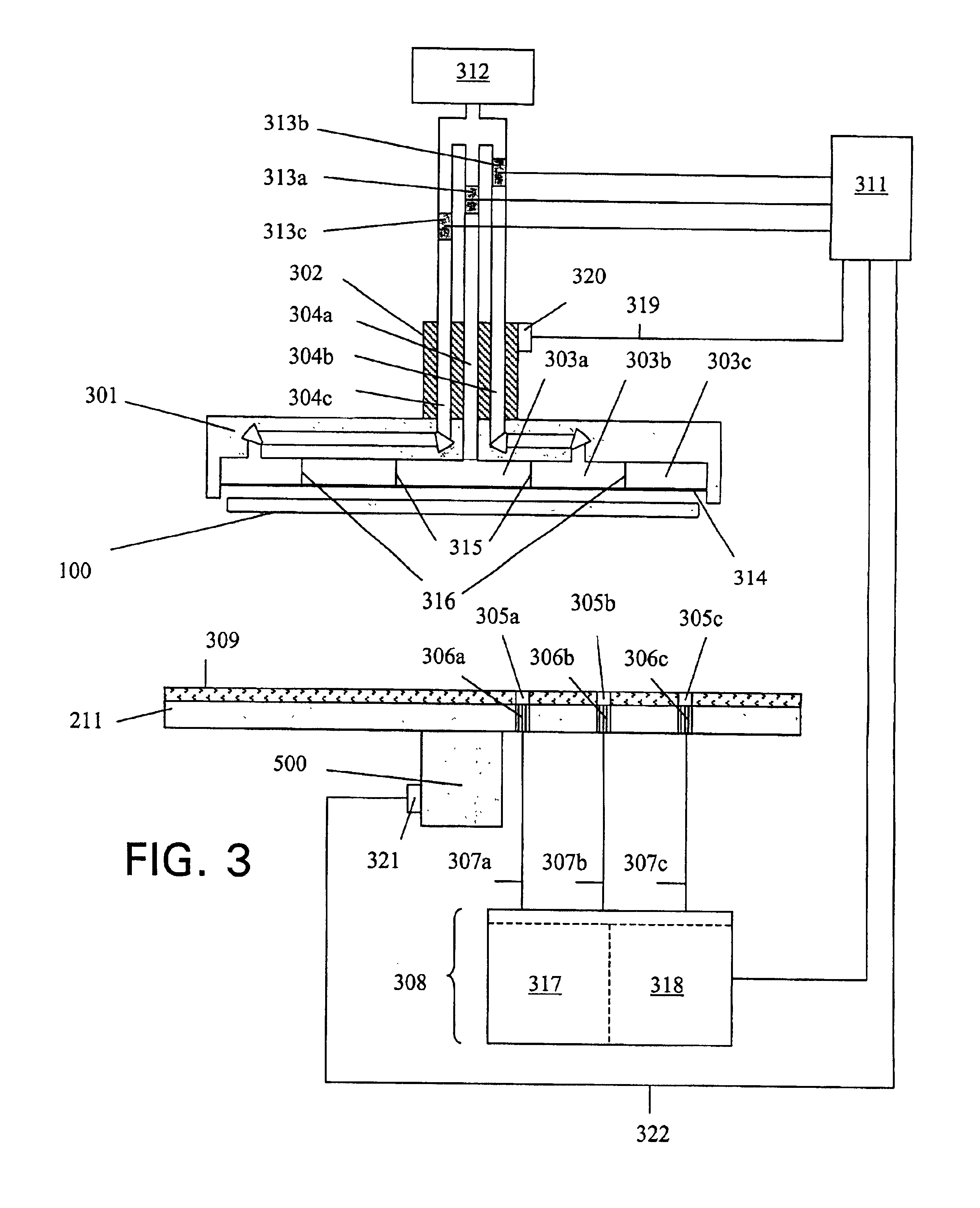
[0016]The wafer is preferably supported on a membrane in a multizone carrier during the planarization process. The multizone carrier may have a plurality of independently controllable pressure plenums behind the membrane. A pump and pressure regulators may be used to control the pressure within one or more of the plenums. The pressing force on the back surface of the wafer may be controlled by controlling the pressure within each of the plenums. Increasing the pressure within a particular plenum will increase the down force on the back surface of the wafer opposite the plenum. The increased down force will increase the removal rate of material on the front surface of the wafer opposite the plenum. The multizone carrier may thus be used to adjust the removal rate of material from the front surface of the wafer during the planarization process. The wafer may also be rotated or oscillated within the carrier by various motors attached to the carrier.
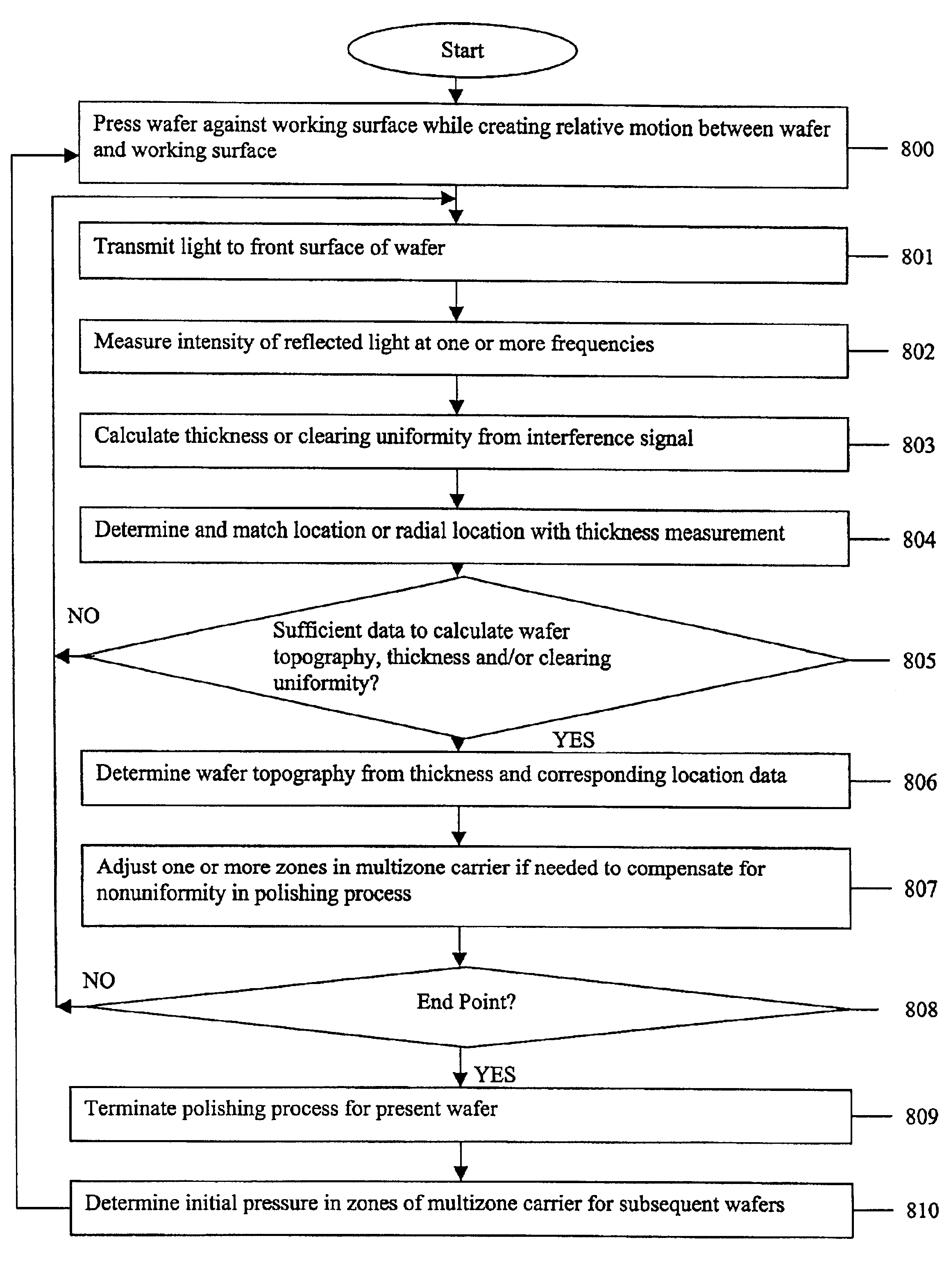
[0023]From the characteristics and corresponding location or radial location, the control system may determine one or more characteristics regarding the front surface of the wafer. For example, the topography, uniformity or thin film thickness may be determined for wafers having a deposited oxide film or the areas still covered by a metal may be determined for wafers having a deposited metal film. The control system may then adjust the pressures in one or more zones within the multizone carrier to improve the resulting local and / or global uniformity of the front surface of the wafer from the polishing process. In general, the pressure may be increased within zones corresponding to areas where increased material removal is desired while the pressure may be decreased within zones corresponding to areas where decreased material removal is desired.

Problems solved by technology

The slicing causes both faces of the wafer to be extremely rough.
A considerable amount of effort in the manufacturing of modem complex, high density multilevel interconnects is devoted to the planarization of the individual layers of the interconnect structure.
Nonplanar surfaces create poor optical resolution of subsequent photolithography processing steps.
Poor optical resolution prohibits the printing of high-density lines.
Another problem with nonplanar surface topography is the step coverage of subsequent metalization layers.
If a step height is too large there is a serious danger that open circuits will be created.
Excessive removal of overburden from the front surface of the wafer, whether a raw sheet film, or an STI, metal or dielectric layer structure on the front wafer surface, may damage the wafer.
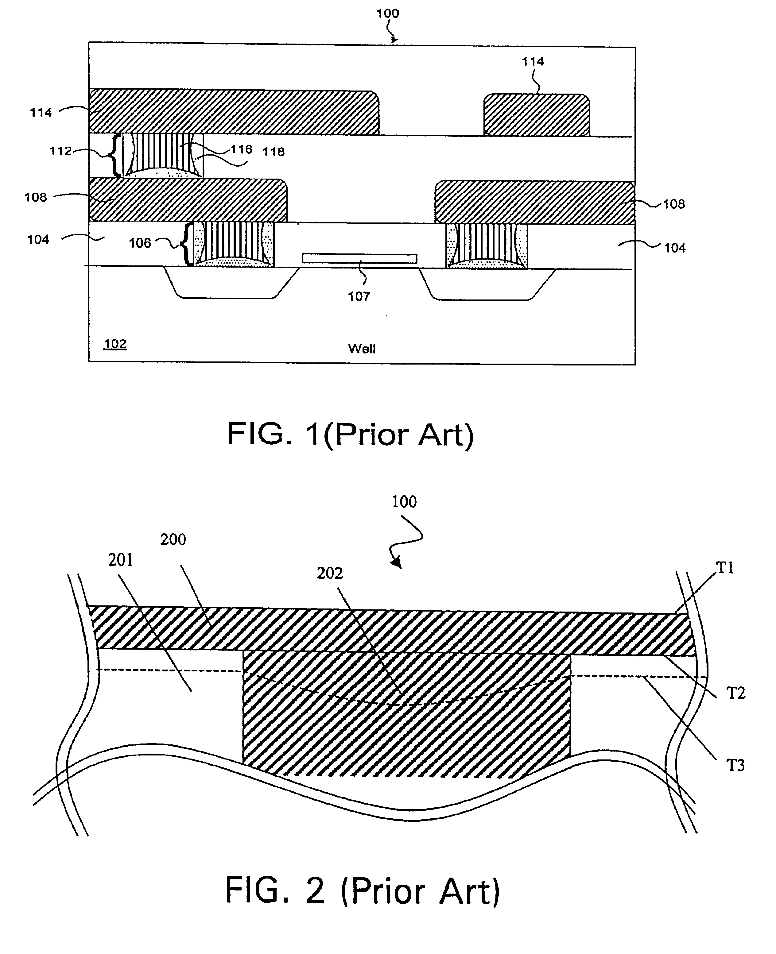
However, if the planarization process is not terminated quickly enough, excessive removal of copper in the interconnects 202 may occur as shown at time T3.
These result in nonuniform clearing of the copper across the front surface of the wafer.
Several problems exist with conventional in situ monitoring techniques that limit their ability to accurately detect the clearing of the copper.
However, these measurements create a system with very poor sensitivity that cannot distinguish high metalization density from mere residual metal.
Applicants also noticed a further problem with some conventional monitoring systems in that they do not associate a measurement with the location on the wafer where the measurement was taken.
Another problem Applicants noticed was that some conventional monitoring systems do not take measurements in fine enough increments along a radial line leaving concentric bands between measurements unmonitored.
Problems in the planarization process typically manifest themselves as bands that are either being polished too quickly or too slowly.
Conventional monitoring systems are not able to detect problem bands that lie totally within unmeasured bands (blind spots).
This creates the very undesirable condition of having potential problem areas that are not detectable.

Method used


Image

  • Multizone carrier with process monitoring system for chemical-mechanical planarization tool
  • Multizone carrier with process monitoring system for chemical-mechanical planarization tool
  • Multizone carrier with process monitoring system for chemical-mechanical planarization tool

Examples


Embodiment Construction

[0034]An improved polishing apparatus and method utilized in the polishing of semiconductor wafers and thin films formed thereon will now be described. In the following description, numerous specific details are set forth illustrating Applicant's best mode for practicing the present invention and enabling one of ordinary skill in the art to make and use the present invention. It will be known, however, to one skilled in the art that the present invention may be practiced without these specific details. In other instances, well-known machines and process steps have not been described in particular detail in order to avoid unnecessarily obscuring the present invention.

[0035]An apparatus for practicing the present invention will now be discussed with reference to FIG. 3. During a planarization process, a wafer 100 may be transported by a carrier 301 to a position adjacent and substantially parallel to a working surface or polishing pad 309. The front surface of the wafer 100 is pressed...


PUM


Abstract

The invention improves a polishing process for a wafer retained in a multizone carrier in a chemical mechanical polishing tool. A light signal is communicated to the front surface of the wafer and the reflected light signal is captured by a metrology instrument. The metrology instrument communicates the intensity of the reflected light to a control system. The location or radial position corresponding to the reflected light signal from the front surface of the wafer may be determined by the control system. From the intensity measurements and corresponding locations, the control system is able to determine an approximate topography of the wafer. The control system may alter the pressure within one or more zones within the multizone carrier to improve the polishing process. The control system may also alter the initial pressures within the multizone carrier for future wafers based on the polishing results from the present wafer.

Description

CROSS-REFERENCES TO RELATED APPLICATIONS[0001]This application is a continuation in part of U.S. Ser. No. 09 / 690,521 filed on Oct. 17, 2000, and of common assignee.TECHNICAL FIELD[0002]The present invention relates generally to semiconductor manufacturing, and more specifically to monitoring in situ a planarization process of a wafer and adjusting the pressure in one or more zones of a multizone carrier to improve the planarization process.BACKGROUND OF THE INVENTION[0003]A flat disk or “wafer” of single crystal silicon is the basic substrate material in the semiconductor industry for the manufacture of integrated circuits. Semiconductor wafers are typically created by growing an elongated cylinder or boule of single crystal silicon and then slicing individual wafers from the cylinder. The slicing causes both faces of the wafer to be extremely rough. The front face of the wafer on which integrated circuitry is to be constructed must be extremely flat in order to facilitate reliable ...

Claims


Application Information

Patent Timeline
Patent Type & Authority Patents(United States)
IPC IPC(8): B24B49/00B24B37/04B24B49/12B24B49/14B24B49/10H01L21/00B24B37/013B24B37/10B24B37/30B24D7/12
CPCB24B37/013B24B37/105B24B37/30B24B49/10B24B49/12B24B49/14B24D7/12H01L21/67253
Inventor LAURSEN, THOMASTROJAN, DANIEL
Owner NOVELLUS SYSTEMS
Why Eureka
Try Eureka