Exhaust gas recirculation for a free piston engine

Inactive Publication Date: 2005-08-09
FORD GLOBAL TECH LLC
View PDF5 Cites 50 Cited by
  • Summary
  • Abstract
  • Description
  • Claims
  • Application Information

AI Technical Summary

Benefits of technology

[0007]An advantage of an embodiment of the present invention is that a free piston engine, with an inherent ability to more easily vary the an opposed piston, opposed cylinder (OPOC) configuration of a free piston engine allows for a more inherently balanced free piston engine, while also being conducive for effective homogeneous charge, combustion ignition (HCCI) engine operation. Such an engine can operate with relatively few major moving parts, generally having less overall friction to overcome during engine operation than a crank engine.
[0008]Another advantage of an embodiment of the present invention is that internal exhaust gas recirculation (EGR) is employed in order to obtain the desired ratio of exhaust gas to air/fuel mixture in th

Problems solved by technology

While these conventional types of engines have seen great improvements in efficiency in recent years, due to the nature of the engines, that efficiency is still limited.
In particular, the power density is limited because the mechanically fixed motion of the pistons fixes the compression ratio.
Moreover, all of the moving parts that direct the movement of the pis

Method used


Image

  • Exhaust gas recirculation for a free piston engine
  • Exhaust gas recirculation for a free piston engine
  • Exhaust gas recirculation for a free piston engine

Examples


second embodiment

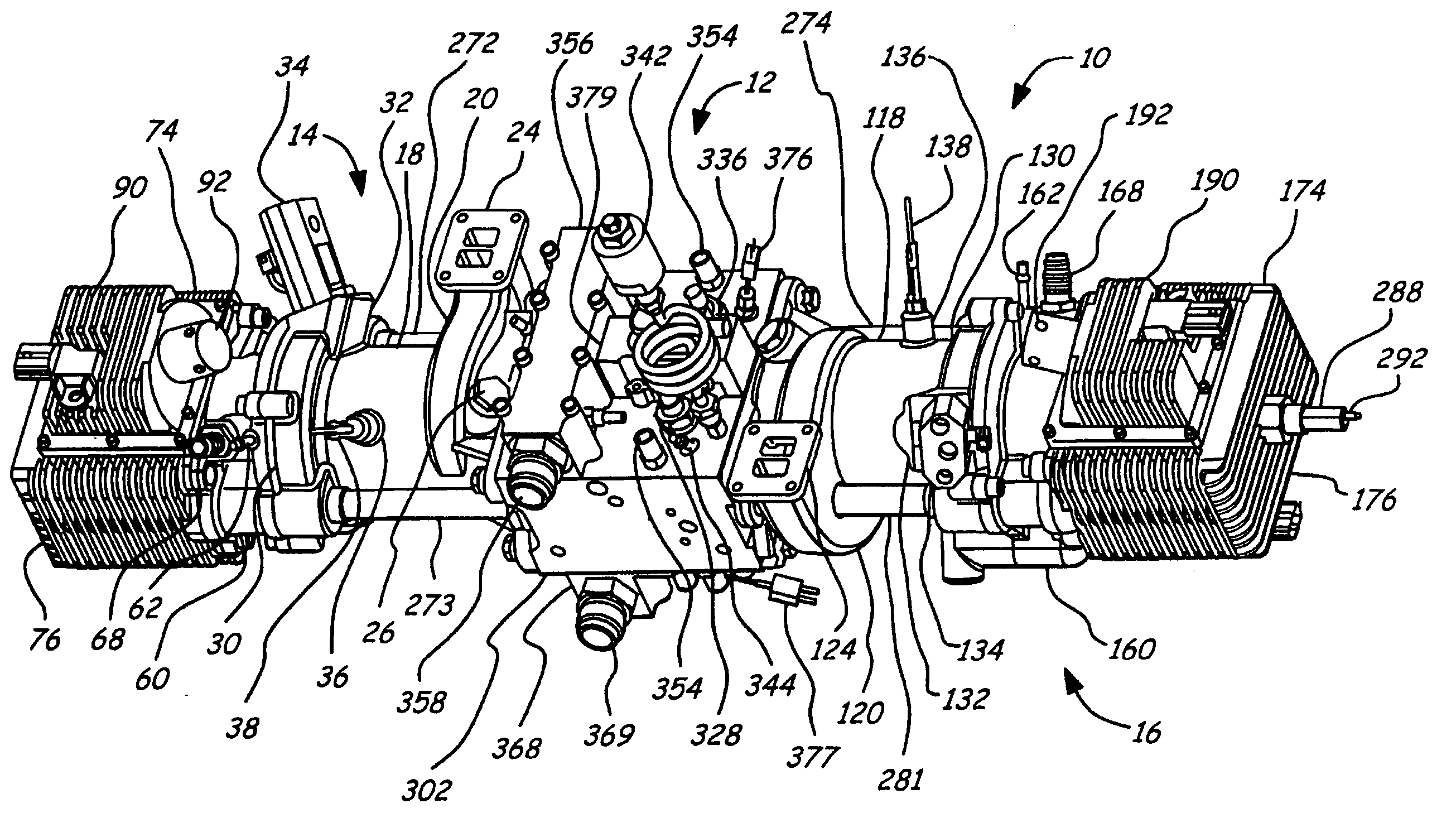
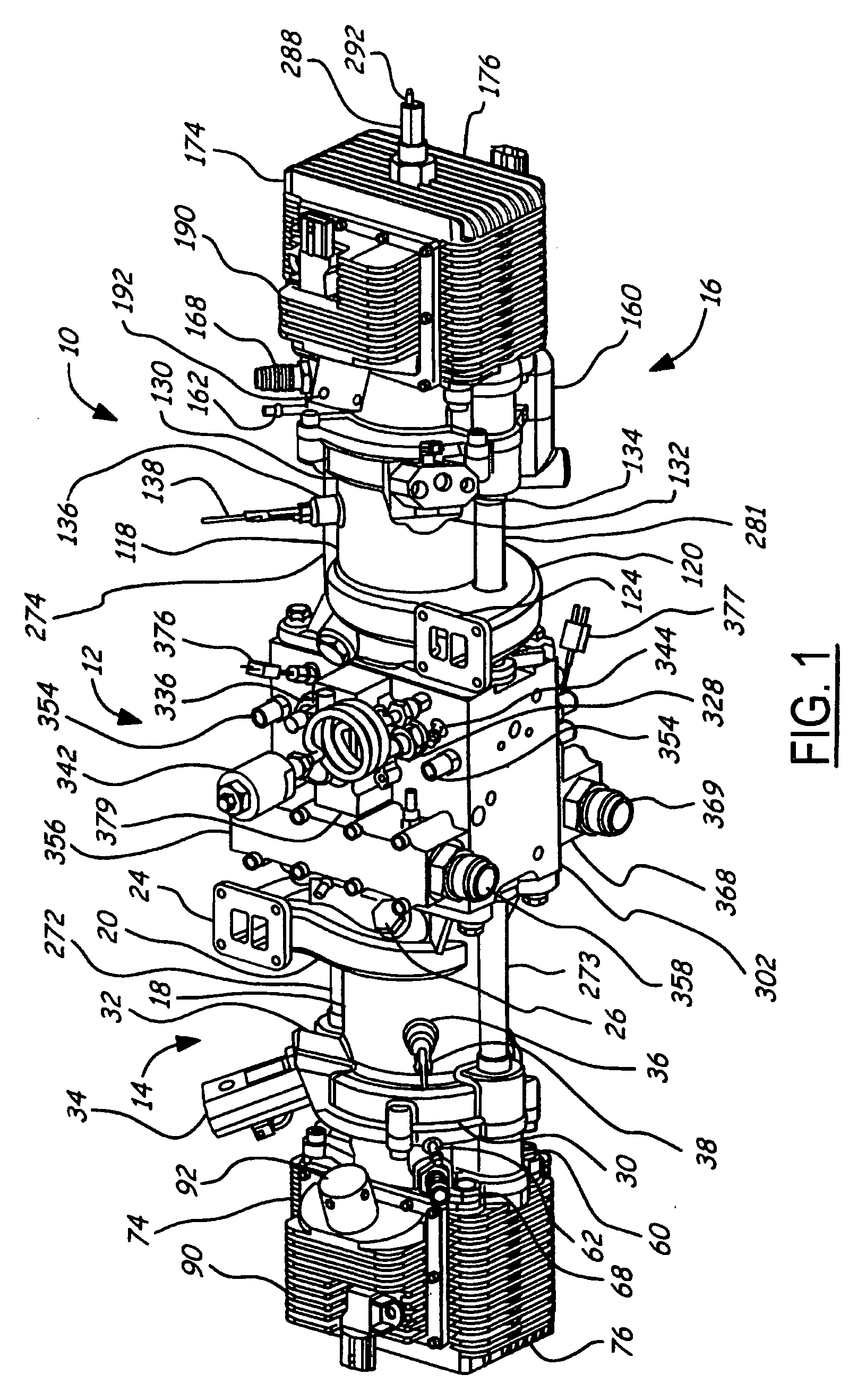
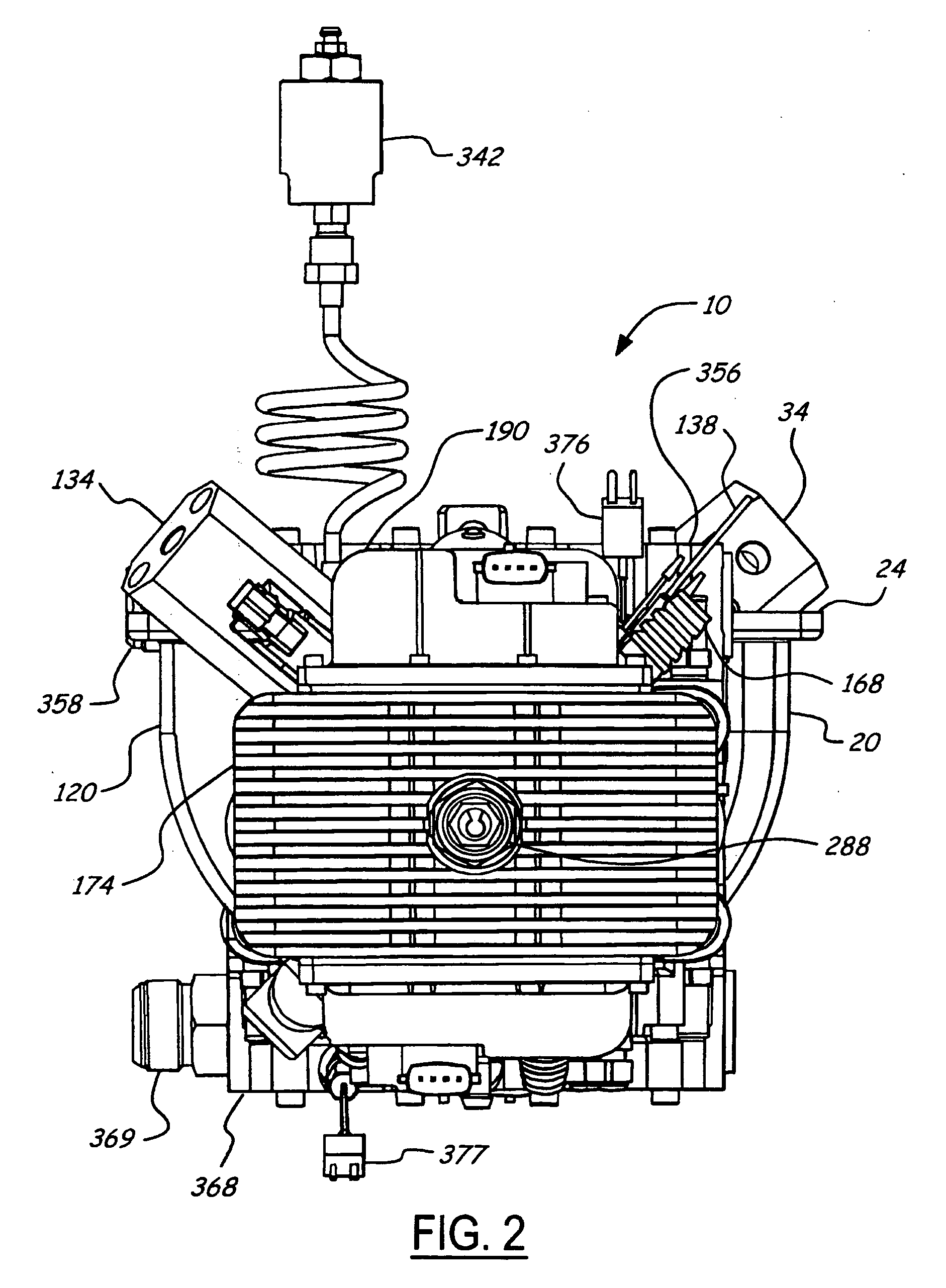
[0114]What distinguishes the second embodiment from the first is that an external EGR system is connected between the exhaust and the air intake. Preferably, the exhaust connection is between the exhaust ports 546 and 547 and the turbine 525 and the air intake connection is between the compressor 597 and the scavenge pumps 74 and 174. A first heat exchanger 598 receives a portion of the exhaust gas from the first engine cylinder 44, cools it and directs it to the intake air stream for the first engine cylinder 44. A second heat exchanger 599 receives a portion of the exhaust gas from the second engine cylinder 144, cools it and directs it to the intake air stream for the second engine cylinder 144. Since a portion of the EGR gas is now coming from the external EGR system, the size and the location of the exhaust ports 546 and 547 will be changed to reduce the amount of internal EGR retained in each engine cylinder 44 and 144.

[0115]Both of the heat exchangers 598 and 599 may be varia...

first embodiment

[0116]The operation of this engine is basically the same as that in the first embodiment except that some of the exhaust gas is diverted to the heat exchangers 598 and 599 and then reintroduced into the cylinders 44 and 144. By cooling some of the exhaust gas that is employed for EGR, the combustion process is slowed. That is, the cooler temperature of the exhaust gas will retard the onset of combustion, which helps to avoid combustion beginning before the pistons have reached their top dead center positions. Thus, energy produced by the combustion is not wasted in stopping and reversing the direction of the pistons.

[0117]Although the fluid employed for the energy storage medium and the control valve has been disclosed in both embodiments as hydraulic oil, other suitable fluids may also be employed if so desired. For example, the fluid may be a gas, with a pneumatic energy storage system for the reservoirs. The fluid may be a refrigerant that can be in the liquid or gaseous state. I...


PUM


Abstract

A free piston engine is configured with a pair of opposed engine cylinders located on opposite sides of a fluid pumping assembly. An inner piston assembly includes a pair of inner pistons, one each operatively located in a respective one of the engine cylinders, with a push rod connected between the inner pistons. The push rod extends through an inner pumping chamber in the fluid pumping assembly and forms a fluid plunger within this chamber. An outer piston assembly includes a pair of outer pistons, one each operatively located in a respective one of the engine cylinders, with at least one pull rod connected between the outer pistons. The pull rod extends through an outer pumping chamber in the fluid pumping assembly and forms a fluid plunger within this chamber. The movement of the inner and outer piston assemblies during engine operation will cause the fluid plungers to pump fluid from a low pressure container into a high pressure chamber as a means of storing the energy output from the engine. Alternatively, the piston assemblies may drive a linear alternator. The exhaust ports for each engine cylinder are sized and located to retain the desired amount of internal EGR in each cylinder without the need for exhaust valves. As an alternative, an external EGR system may supplement the internal EGR in order to obtain the desired EGR at the desired temperature.

Description

BACKGROUND OF INVENTION[0001]The present invention relates to free piston engines.[0002]Conventionally, internal combustion engines have operated with the motion of the pistons mechanically fixed. For example, a conventional internal combustion engine for a motor vehicle includes a crankshaft and connecting rod assemblies that mechanically determine the motion of each piston within its respective cylinder. This type of engine is desirable because the position of each piston is know for any given point in the engine cycle, which simplifies timing and operation of the engine. While these conventional types of engines have seen great improvements in efficiency in recent years, due to the nature of the engines, that efficiency is still limited. In particular, the power density is limited because the mechanically fixed motion of the pistons fixes the compression ratio. Moreover, all of the moving parts that direct the movement of the pistons (and camshafts and engine valves as well) crea...

Claims


Application Information

Patent Timeline
IPC IPC(8): F02M25/07F02B1/12F02B25/06F02B25/08F02B71/04
CPCF02B25/06F02B25/08F02B71/04F02B1/12F02M25/0707F02M25/0732F02M25/0752F02M26/01F02M26/05F02M26/24
Inventor PENG, LIXINCARLSON, CLIFF
Owner FORD GLOBAL TECH LLC
Why Eureka
Try Eureka