Light detection device

a technology of light detection and detection device, which is applied in the field of optical detection, can solve the problems of short life of arc lamps, damage to other electronic components of the system, and the inability to detect light sources, etc., and achieve the effect of improving flexibility and/or reading speed

Inactive Publication Date: 2005-08-16
MOLECULAR DEVICES
View PDF19 Cites 53 Cited by
  • Summary
  • Abstract
  • Description
  • Claims
  • Application Information

AI Technical Summary

Benefits of technology

[0014]The invention provides apparatus and methods for optical detection with improved flexibility and / or read speed, including mechanisms for selecting and switching between multiple excitation wavelengths and / or simultaneously reading from a plurality of sample sites.

Problems solved by technology

Unfortunately, these light sources suffer from a number of shortcomings.
The gas used in arc lamps typically is under high pressure, so that explosion is always a danger, and the associated power supplies may produce transients that can damage other electronic components of the system.
The lifetime of arc lamps may be short, so that the lamps must be changed frequently.
Moreover, typical arc lamps (including flash arc lamps) suffer from intensity instability, with short-term noise of several percent, which is much worse than good lasers such as laser diodes and diode pumped solid-state lasers, with short-term noise of typically less than 0.5%.
In addition, lamps have a slow and steady long-term decay of intensity, whereas lasers normally exhibit a constant intensity up until catastrophic failure.
The spectral output of some arc lamps and most lasers is very limited, so that desired excitation wavelengths may not be available.
Moreover, the procedure for switching or tuning between these wavelengths can be so cumbersome and impractical that some experimentalists have resorted to the expensive alternative of incorporating multiple lasers into their instrumental setups.
Time spent during alignment and subsequent waiting periods is downtime because it is time during which data cannot be collected from the sample.
However, reading with the scanner is slow, because samples are analyzed well by well, and reading with the wide-field imager reduces intensities, because excitation light is distributed to areas between or outside the samples.
Reduced intensities may decrease signal-to-noise ratios, decreasing reliability, especially with less intense nonlaser light sources.
Prior art instrument systems also may be limited because it may be difficult to change the emission filter to correspond to a change in excitation wavelength.

Method used


Image

  • Light detection device
  • Light detection device
  • Light detection device

Examples


example 1

Construction of Prototype Apparatus

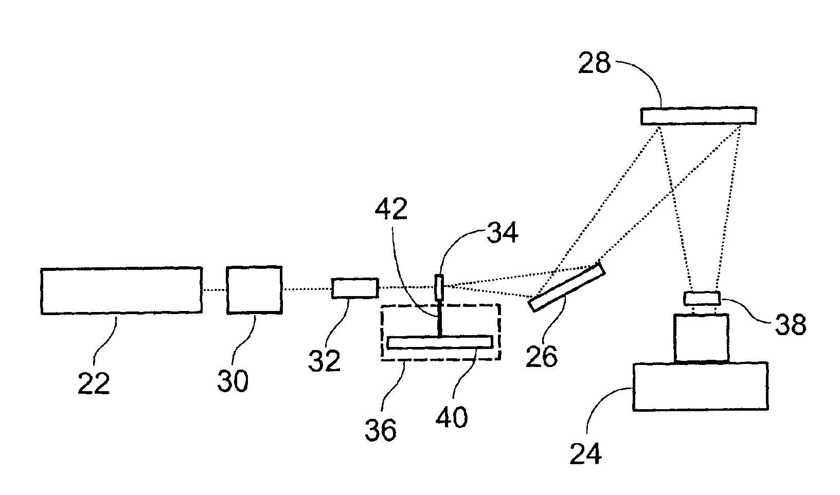
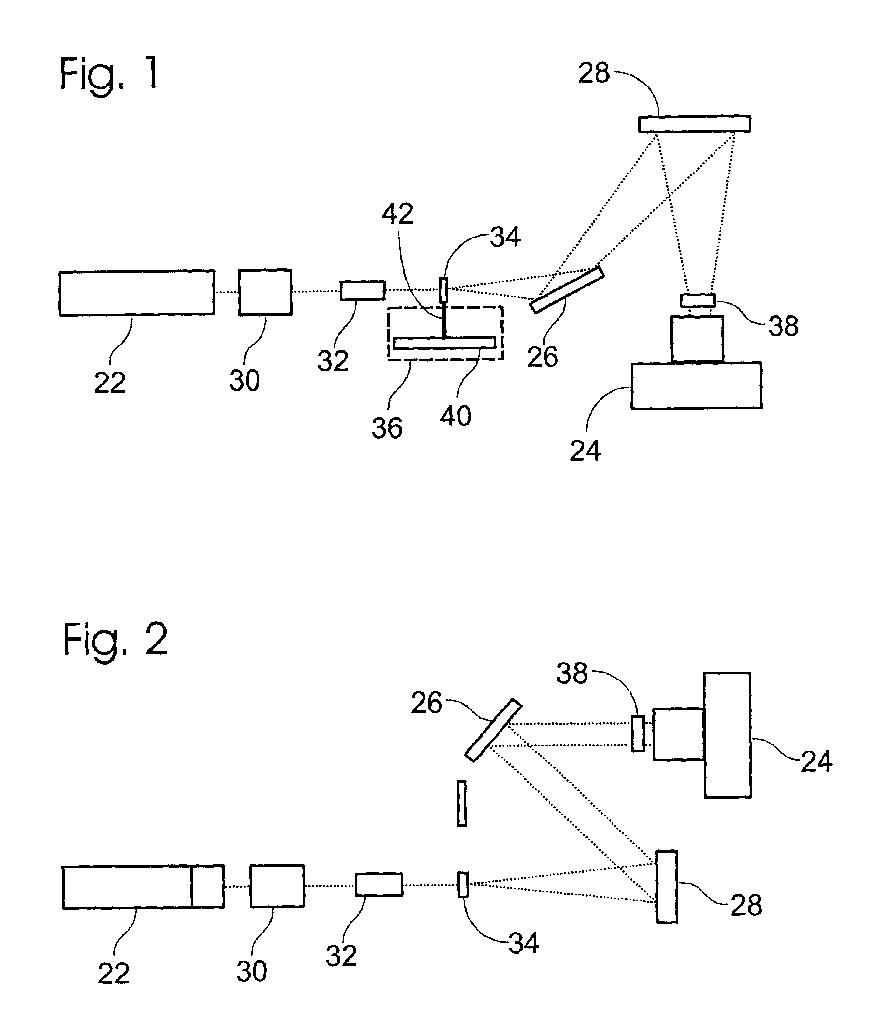
[0066]This example, illustrated in FIGS. 1 and 2, describes two alternative apparatuses constructed in accordance with aspects of the invention. The apparatuses each include a light source, a wavelength converter, an optical pattern generator, a detector, and an optical relay structure adapted to transmit light to and / or from these optical elements and an examination site.

[0067]The light source and wavelength converter includes a pulsed YAG laser (1060 nm) with harmonic generators that created a third harmonic at 353 nm and a CONTINUUM SURELITE II Optical Parametric Oscillator, which is pumped by the YAG laser. The OPO has a micrometer knob and a look-up table allowing selection of any wavelength from 400-2500 nm.

[0068]The optical pattern generator includes a diffractive optic (commercially available from Edmund Scientific) that produces an 8×8 array of beamlets from the single incoming beam. The divergence angle of the exit beamlets is dependent o...

example 2

Analysis of Illumination Power and Uniformity Across a Microplate

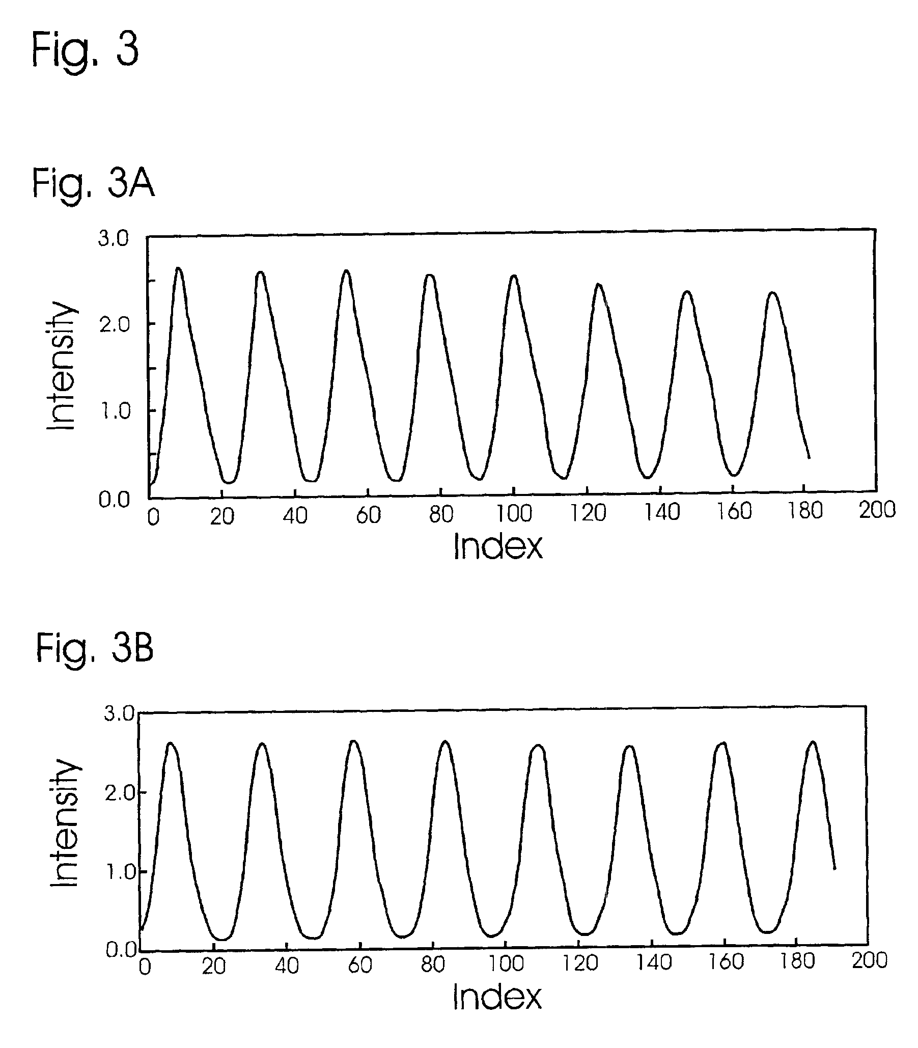
[0072]This example, illustrated in FIG. 3, describes the analysis of illumination power and uniformity across a microplate.

[0073]The power and uniformity of illumination produced by the apparatus were determined using a standard 384-well calibration microplate, i.e., a multiwell microplate that had been coated with a uniform layer of fluorescein. The illumination laser was run at maximum power output, internally triggered at a pulse rate of 10 Hz. The average power out of the OPO was measured at 250 mW, or about 25 mJ / pulse. The time-averaged illumination intensity was calculated to be approximately 0.22 mW / mm2, by considering the illuminated area to be approximately 1200 mm2 (calculated as the sum of the cross-sectional areas of all of the microplate wells, i.e., π×(1 mm)2×384).

[0074]The fluorescence of the calibration microplate was analyzed by recording and analyzing a series of exposures. Specifically, fluorescence...

example 3

Laser Triggering

[0076]This example, illustrated in FIGS. 4 and 5, describes laser (and camera) triggering.

[0077]The illumination laser was utilized in several different operational modes. For the particular laser used in these experiments, the power output and shot-to-shot consistency were maximized when the laser was triggered internally, with the flash lamps firing at a predetermined steady rate close to about 10 Hz. This firing mode produced relatively consistent laser pulse intensity, as shown in FIG. 4. The coefficient of variance of the pulse intensity data in this case was about 142 / 2500, or about 0.057, computed as the standard deviation in the measured results divided by the associated mean. In some experiments, due to idiosyncrasies of the experimental set up, the laser was not triggered internally, but instead was triggered externally from the camera by using the “shutter open” signal. This trigger protocol insured that the laser fired while the shutter was open, resultin...


PUM

PropertyMeasurementUnit
wavelengthsaaaaaaaaaa

Abstract

Apparatus and methods for optical illumination and/or detection with improved flexibility and/or read speed. The apparatus and methods may include mechanisms for selecting and switching between multiple excitation wavelengths and/or simultaneously reading from a plurality of sample sites. The apparatus and methods may be used with microplates, PCR plates, cell culture plates, biochips, chromatography plates, microscope slides, and other substrates for high-throughput screening, genomics, SNPs analysis, pharmaceutical research and development, life sciences research, and other applications.

Description

CROSS-REFERENCE[0001]This application is based upon and claims the benefit under 35 U.S.C. § 119 and all applicable foreign and international law of the following U.S. provisional patent application, which is hereby incorporated by reference in its entirety for all purposes: Ser. No. 60 / 244,012, filed Oct. 27, 2000.[0002]This application hereby incorporates by reference in their entirety for all purposes the following U.S. Pat. No. 5,355,215, issued Oct. 11, 1994; and No. 6,097,025, issued Aug. 1, 2000.[0003]This application hereby incorporates by reference in their entirety for all purposes the following U.S. patent application Ser. No. 09 / 337,623, filed Jun. 21, 1999; Ser. No. 09 / 349,733, filed Jul. 8, 1999; Ser. No. 09 / 478,819, filed Jan. 5, 2000; Ser. No. 09 / 596,444, filed Jun. 19, 2000; Ser. No. 09 / 710,061, filed Nov. 10, 2000; Ser. No. 09 / 722,247, filed Nov. 24, 2000; Ser. No. 09 / 759,711, filed Jan. 12, 2001; Ser. No. 09 / 765,869, filed Jan. 19, 2001; Ser. No. 09 / 765,874, filed...

Claims


Application Information

Patent Timeline
Patent Type & Authority Patents(United States)
IPC IPC(8): G01N21/64G01J1/58G01J1/00G01J3/30G02BH01L29/22
CPCG01N21/6456
Inventor JACKSON, III, JOSEPH H.HAFEMAN, DEAN G.FRENCH, TODD E.
Owner MOLECULAR DEVICES
Why Eureka
Try Eureka