[0003]It has been found that the video imaging subsystems of radiographic and
fluoroscopic imaging systems are highly susceptible to the effects of the cables used to interconnect their various components. These cables vary in length depending on the particular installation site, and therefore the final installed cable length is not known at the time the
video image chain is factory calibrated. If the cable length imparts conditions on the video chain which are different from those that were used to factory-calibrate the video subsystem,
image quality at the installation site can be substantially degraded. As a result, the video imaging subsystem requires additional
field calibration and / or replacement of components until image quality is raised to an acceptable level, and this greatly increases the time and
cost burden of installation.
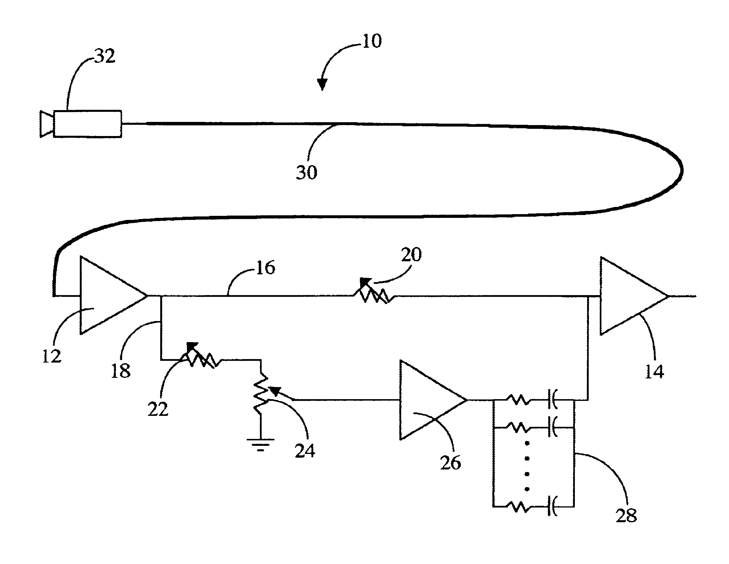
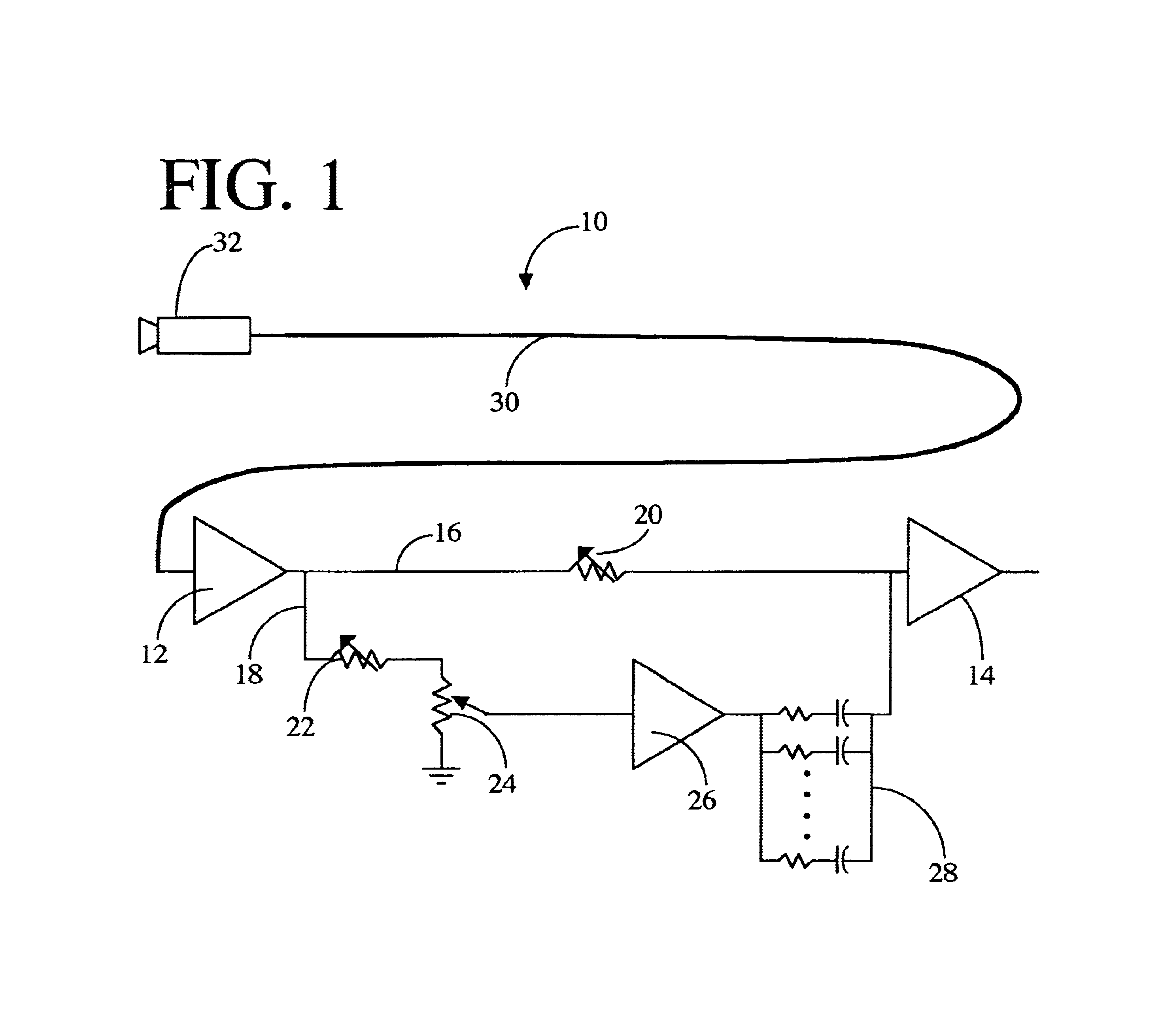
[0004]The cable compensator, which is defined by the claims set out at the end of this disclosure, is intended to be situated in a signal path of a video imaging
system (such as the one in a radiographic / fluoroscopic imaging system) so that
signal integrity is not degraded by the different cable lengths that might be present in the signal path at the installation site. The cable compensator may be situated in the signal path and set to an appropriate setting corresponding to the installed cable length, and will thereby equalize the video subsystem's
frequency response with high precision from DC to a maximum frequency so that gain is unaffected across the range of video subsystem operating frequencies. An exemplary cable compensator in accordance with the invention includes a first path wherein a means for adjusting low frequency gain is situated between an input end and an output end, and a second path which includes an input end and an output end with several components situated therebetween: a means for adjusting high frequency gain, a
variable resistance, and a
parallel array of at least two capacitances. An output
amplifier is also provided into which the output ends of the first and second paths are summed. The
parallel array of capacitances, when taken in conjunction with the output
amplifier and with one or more resistances provided in series with the capacitances, effectively allows the second path to act as an array of high-pass filters. As will be described at greater length later in this disclosure, when
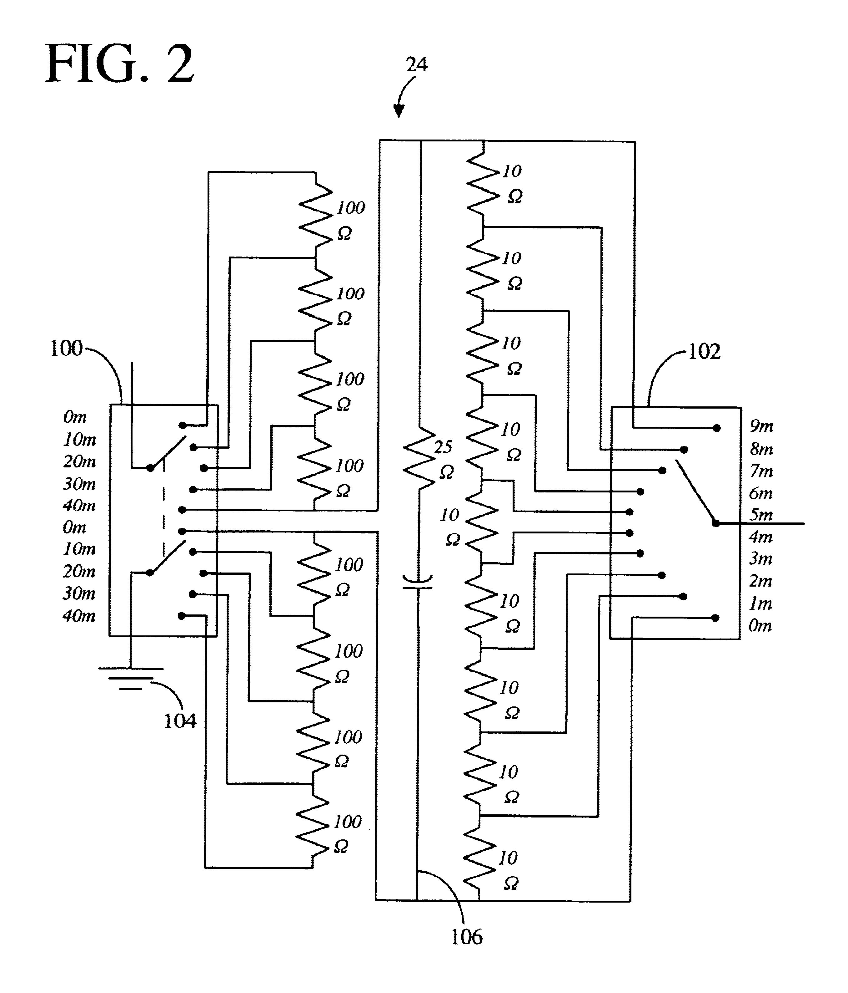
capacitance and resistance values are appropriately chosen and the low and high frequency gain adjustment means are properly tuned, the compensator can be situated in a signal path, the
variable resistance of the second path can be set to a resistance value proportional to the length of the variable-length cable in the signal path, and the compensator will then provide a compensator output signal which is substantially similar to the cable input signal across the range of
target signal frequencies. Most preferably, the variable resistance in the second path is provided in the form of a discretely variable resistance (e.g., a switched
resistor divider array) and the low and high frequency gain adjustment means are provided by continuously variable resistances (e.g., rheostats). In addition, resistances are preferably provided in series with each of the capacitances in the parallel
capacitor array (i.e., the array is formed of parallel RC series components), and this array is isolated from the other resistances in the second path by a buffer so that the other resistances do not contribute to the RC filtering characteristics.
[0005]The cable compensator is highly advantageous since it allows video signal paths, such as the video
imaging chain of an X-ray imaging system, to be readily calibrated for any final cable length to be used at an installation site (this cable length being unknown at the time the system components and compensator are manufactured). Installation and
field calibration time is greatly decreased, and image quality for a given X-ray system can be made consistent from one installation site to another. The compensator also avoids the situation where video subsystems are unnecessarily replaced because deficient image quality is seen as arising from a flaw in the video chain, but where it actually arises because the video chain is inappropriately calibrated for the cable length used at the installation site. Further advantages, features, and objects of the invention will be apparent from the following detailed description of the invention in conjunction with the associated drawings.

