Interference measuring device

a measurement device and interference technology, applied in measurement devices, instruments, electric discharge tubes, etc., can solve the problems of large affecting measurement, increasing the size of the optical system, and essentially small measurement error inherent in the interference system, and achieve high precision and obtain high-precision correction effects with eas

Inactive Publication Date: 2005-09-27
JAPAN SCI & TECH CORP +1
View PDF11 Cites 6 Cited by
  • Summary
  • Abstract
  • Description
  • Claims
  • Application Information

AI Technical Summary

Benefits of technology

[0043]Thus, if a shielding plate is placed on the plane equivalent to the observing plane, to be formed between the laser light source and the biprism, so that the wavefront splitting boundary of the wavefront splitting element lies within the shadow thereof, it is possible to avoid Fresnel diffracted waves by the shielding plate, and to implement the situation where Fresnel diffraction will not occur at the wavefront splitting element.
[0044]In general, the measurement is carried out under the condition where a focus is achieved on a sample. Therefore, in this case, the shielding plate is placed on the sample plane, or the plane equivalent to the sample plane, to be formed between the coherent beam source and the wavefront splitting element. In this step, the shielding plate is not required to be exactly on the observing plane, or the plane equivalent to the sample plane. Fresnel diffracted waves converge to one point at the source, and hence there occurs very little spreading of Fresnel diffracted waves in the very nearby region thereof. Therefore, the Fresnel diffracted waves due to the edges of the shielding plate is allowable so long as they do not affect the portion to be measured which has undergone phase changes due to the sample on the observing plane.
[0045]A second means for removing the phase changes due to the interference system is the following method. Namely, two measurement results for the case where there is a sample are obtained by shifting the positional relationship between the sample image and the interference fringes. The difference between the two results is integrated with respect to the direction of shift, thereby to obtain the measurement result from which the errors inherent in the interference system has been removed. Particularly, this method is combined with the method referred to as a fringe scanning method wherein the phase change distribution due to the sample is measured with high precision from a plurality of interference images having gradually and successively shifted relative positional relationships between the sample image and the interference fringes with respect to each other. As a result, it is possible to obtain high-precision correction effects with ease because the foregoing two types of measurement results can be obtained from a series of interference image groups.

Problems solved by technology

Accordingly, the measurement error inherent in the interference system is essentially small.
As a result, for the amplitude splitting type, the optical system is increased in size, and becomes complicated.
However, with the wavefront splitting type interference element, the Fresnel diffracted waves from the wavefront splitting boundary very largely affects the measurement.

Method used


Image

  • Interference measuring device
  • Interference measuring device
  • Interference measuring device

Examples


embodiment 1

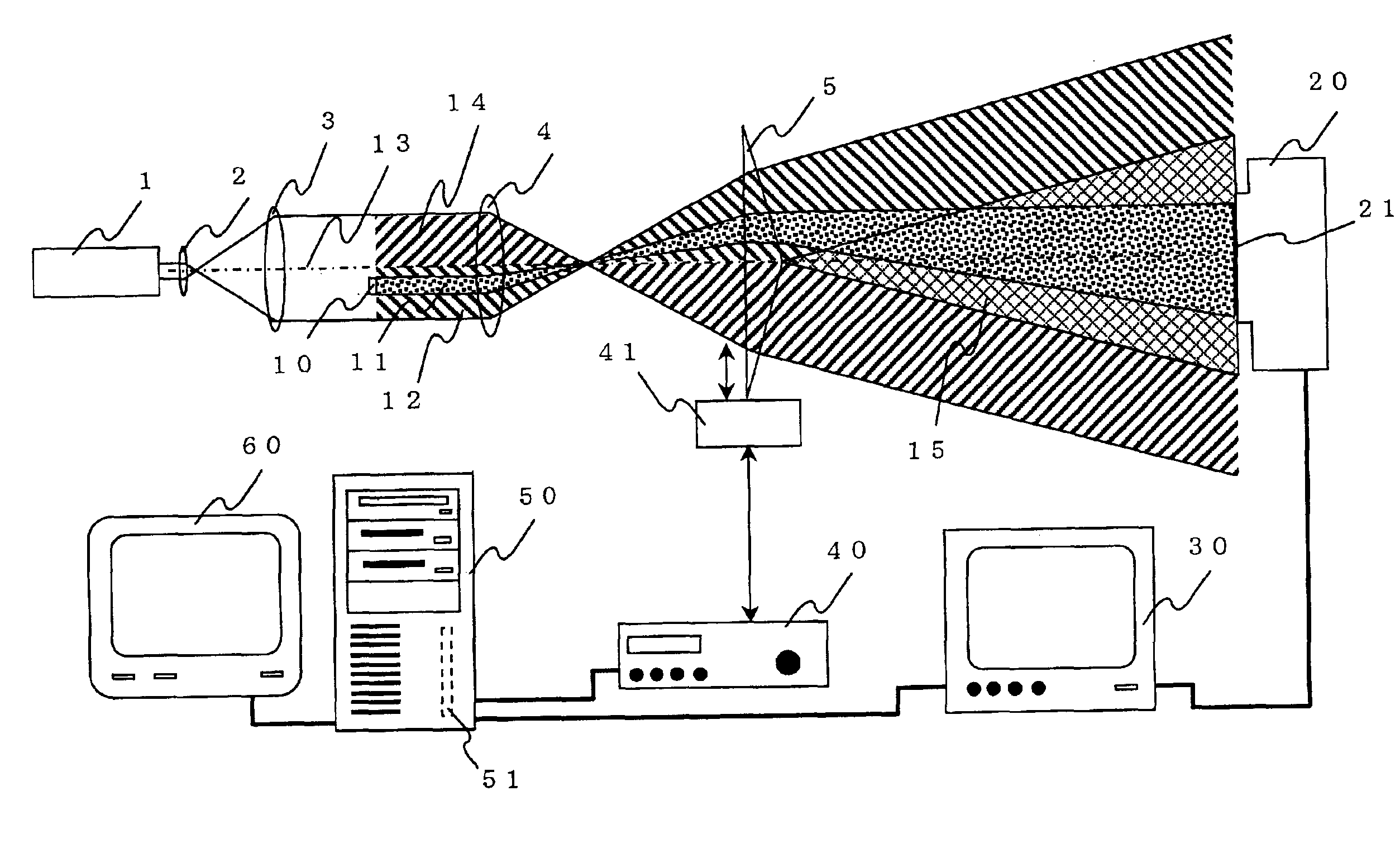
[0059]A first embodiment of the present invention will be described by reference to a fringe scanning laser interference measuring device based on the movement of a biprism shown in FIG. 6. In this embodiment, a biprism 5 which is a wavefront splitting element was used as an interference element, and a beam shielding plate 100 in such a form as to act as a shield against a beam to be irradiated to the wavefront splitting boundary of the biprism was disposed on the sample plane as a means for removing the phase change distribution due to the interference element. The phase distribution of a sample image or a sample-transmitted beam is generally observed at the positive focal point. Herein, the shielding plate 100 was therefore placed on the sample plane equivalent to an observing plane, so that the positive focal point image of a sample was formed directly on the image pickup surface of an image pickup element 20. Herein, there was employed a one-stage magnifying system in which one ...

embodiment ii

[0061]FIG. 7 shows a second embodiment of the present invention. This is so configured that the magnifying lens system of the fringe scanning interference measuring device shown in FIG. 1 has been changed to a two-stage system of an objective lens 4 and a magnifying lens 6 as far as the components shown in this figure concerned. Herein, a reference numeral 25 denotes an intermediate magnified image, and 26 denotes the position at which the intermediate magnified image is formed. A biprism 5, which is a wavefront splitting element, was used as an interference element. A biprism micro-movement mechanism 41 for shifting the relative positional relationship between a sample image and the interference fringes was disposed at an observing plane as a means for removing the phase change distribution due to the interference element. In addition, a calculating device 50 has functions of storing a first interference image, and a second interference image shifted from the first interference ima...

embodiment iii

[0077]On the other hand, the second phase distribution of the expression (6) is shifted by −Δx in the calculating device, and subtracted from the first phase distribution of the expression (5). The resultant value is then normalized by Δx. As a result, it is also possible to directly obtain the form given by differentiating the phase change distribution due to the sample as expressed as the following expression (14): ϕ⁡(x,y)-ϕ⁡(x-Δ⁢ ⁢x,y)Δ⁢ ⁢x(14)

[0078]This is basically equivalent to that for the case where the sample 10 has been moved by −Δx in place of moving the biprism 5 of Embodiment 2 by +Δx for forming the second interference image except for the opposite edges along the x direction of the image. Therefore, the sample 10 may also be moved. FIG. 9 shows an embodiment in which the fringe scanning interference method is implemented by micro-moving the sample 10. The configuration of FIG. 9 is different from the configuration of FIG. 6 only in that the micro-movement control mech...


PUM


Abstract

In an interference measuring device, which includes: a coherent beam generating source; a sample to be measured; a lens system for forming an image of the sample to be measured on an observing plane; an interference element for splitting a coherent beam into two systems, and forming an interference image on the observing plane or a plane equivalent thereto; an image pickup element for picking up the interference image on the observing plane; and a calculating device having functions of capturing and storing the interference image converted to electric signals by the image pickup element, and determining the phase distribution changed by the sample to be measured from the interference image by calculation, wherein a means for removing the phase change distribution due to the interference element is provided.

Description

BACKGROUND OF THE INVENTION[0001]The present invention particularly relates to an interference measuring device belonging to a wavefront splitting type among interference measuring devices.[0002]The interferometers often used for interference measurement using a laser include: Twyman-Green interferometer (ex., reference literature 1: Subfringe Interference Measurement Basic Theory, Optics 13 (1984) p.p. 55-65, or reference literature 2: Quantitative Phase Analysis in Electron Holographic Interferometry, Appl. Opt. 26 (1987) 377-382), Mach-Zehnder interferometer (reference literature 3: Interference Electron Microscopy by Means of Holography, Japan, J. Appl. Phys. 18 (1979) 2291-2294), further, Fizeau interferometer (reference literature 4: High Resolution Phase Measuring Laser Interferometric Microscope for Engineering Surface Metrology, SPIE 1009 (1988) 35-44), and the like. Any of the interferometers is of an amplitude splitting type which splits one beam into two beams, a beam tr...

Claims


Application Information

Patent Timeline
Patent Type & Authority Patents(United States)
IPC IPC(8): G01B11/24
CPCG01B11/2441H01J2237/1514
Inventor ENDO, JUNJICHEN, JUN
Owner JAPAN SCI & TECH CORP
Why Eureka
Try Eureka