Combusting hydrocarbons excluding nitrogen using mixed conductor and metal hydride compressor

a technology of metal hydride compressor and hydrocarbon fuel, which is applied in the ignition of turbine/propulsion engine, separation process, lighting and heating apparatus, etc. it can solve the problems of limiting the efficiency of most rankine system power plants to less than about 35%, large heat exchangers are needed, and limiting the efficiency of the brayton system to only about 40%, so as to improve the operating efficiency of the combustion engine

Inactive Publication Date: 2005-10-04
CHENTEK
View PDF9 Cites 30 Cited by
  • Summary
  • Abstract
  • Description
  • Claims
  • Application Information

AI Technical Summary

Benefits of technology

[0015]According to one aspect of the present invention, there is provided a combustion engine that extracts hydrogen from exhaust fluid for recirculation through an exhaust turbine. Exhaust fluid expands in the exhaust turbine to cause a turbine rotor to rotate. The exhaust fluid results from the combustion of hydrocarbon fuel. The combustion engine is configured to combust hydrocarbons excluding nitrogen in order to eliminate NOx emissions. The combustion engine uses a mixed conductor and operates with hydrogen as a working gas wherein the mixed conductor limits the rate at which oxygen can react with the hydrocarbon fuel.
[0016]The combustion engine is also configured to prevent the formation of hydrocarbon and CO emissions by reacting products with steam. Water gas shift reaction catalysts are further utilized in the combustion engine in order to prevent the formation of volatile organic compounds (VOC's)—organic chemicals that have a high vapor pressure and which easily form vapors. The water gas shift reaction catalysts convert VOC emissions to hydrogen.
[0022]Metal hydride material in the first and second metal hydride hydrogen compressors allows the hydrogen in the exhaust fluid to be extracted from the exhaust fluid and absorbed into the metal hydride material at a low temperature. The metal hydride material in the first and second metal hydride hydrogen compressors promotes the release of the absorbed hydrogen at elevated temperature and pressure when the metal hydride material is heated. A desiccant may be fluidly connected between the gas absorber and the second metal hydride hydrogen compressor to remove moisture from the hydrogen prior to the second metal hydride hydrogen compressor receiving the hydrogen. A gas desorber may receive the exhaust fluid and extract carbon dioxide from the water and vent a remaining portion of the carbon dioxide to atmosphere.
[0028]The pressurized extracted hydrogen may be recirculated through the exhaust turbine to improve the operating efficiency of the combustion engine as mentioned above. The pressurized extracted hydrogen may be further heated by recirculating the hydrogen along the retentate side of the mixed conductor during combustion of the hydrocarbon fuel.

Problems solved by technology

Unfortunately, the large amount of heat that is lost during the condensation of the steam limits most Rankine system power plants to an efficiency of less than about 35%.
One disadvantage of the closed-cycle Brayton system is that a large heat exchanger is needed in order to transfer heat from an external combustion source to the working gas.
Unfortunately, the consumption by the compressor of a large portion of mechanical work produced by the turbine limits the efficiency of the Brayton system to only about 40%.
Furthermore, the components required for compressing the air occupy about one-half of the total volume of the Brayton engine and account for approximately one-half of its total cost.
The internal combustion engines of the Otto and Diesel systems include complex reciprocating piston equipment for intermittently combusting hydrocarbon fuel with the air.
However, such systems produce excessive noise and vibration with the additional drawback of large frictional losses occurring between the pistons and seals, thus limiting the efficiency the Otto and Diesel systems to about 40%
Unfortunately, exhaust fluids that are a byproduct of the combustion reaction may contain emissions that are harmful to the environment and to human health.
The higher the inefficiency of the combustion engine, the greater the amount of unreacted fuel that is emitted from the combustion reaction and the greater the amount of fuel that is consumed per unit of power that is produced by the engine.
In addition, the increase in fuel consumption also increases the cost of operating the engine.
Furthermore, because the hydrocarbon fuel typically utilized in most combustion engines is comprised of non-renewable fossil fuels, poor fuel consumption has an adverse impact on the environment in that less accessible fuel sources must be extracted from ecologically sensitive locations around the world.
Exposure to high levels of CO is associated with visual impairment in humans.
NO2 can irritate the lungs and lower resistance to respiratory infections.
Reports indicate that the continuing increase of NO2 and CO2 concentrations in the atmosphere will lead to a dangerous interference with the planet's climate system, resulting in more frequent and stronger storms, floods and droughts that may threaten food production while simultaneously increasing insect-borne disease as a hazard to human health.
While this method is effective in eliminating harmful emissions, the overall efficiency of the engine is not improved.
Furthermore, after-treatment of exhaust requires additional emissions control components that add weight and complexity to the combustion engine as they must be configured to withstand the increased temperatures occurring within the exhaust stream.
Another drawback to this approach is the injection of air into the exhaust stream results in an increase in NOx production.
However, storing and / or transporting NH3 near a power plant or in an automobile is not practical from both a complexity and operational standpoint nor is it cost effective.

Method used


Image

  • Combusting hydrocarbons excluding nitrogen using mixed conductor and metal hydride compressor
  • Combusting hydrocarbons excluding nitrogen using mixed conductor and metal hydride compressor
  • Combusting hydrocarbons excluding nitrogen using mixed conductor and metal hydride compressor

Examples


Embodiment Construction

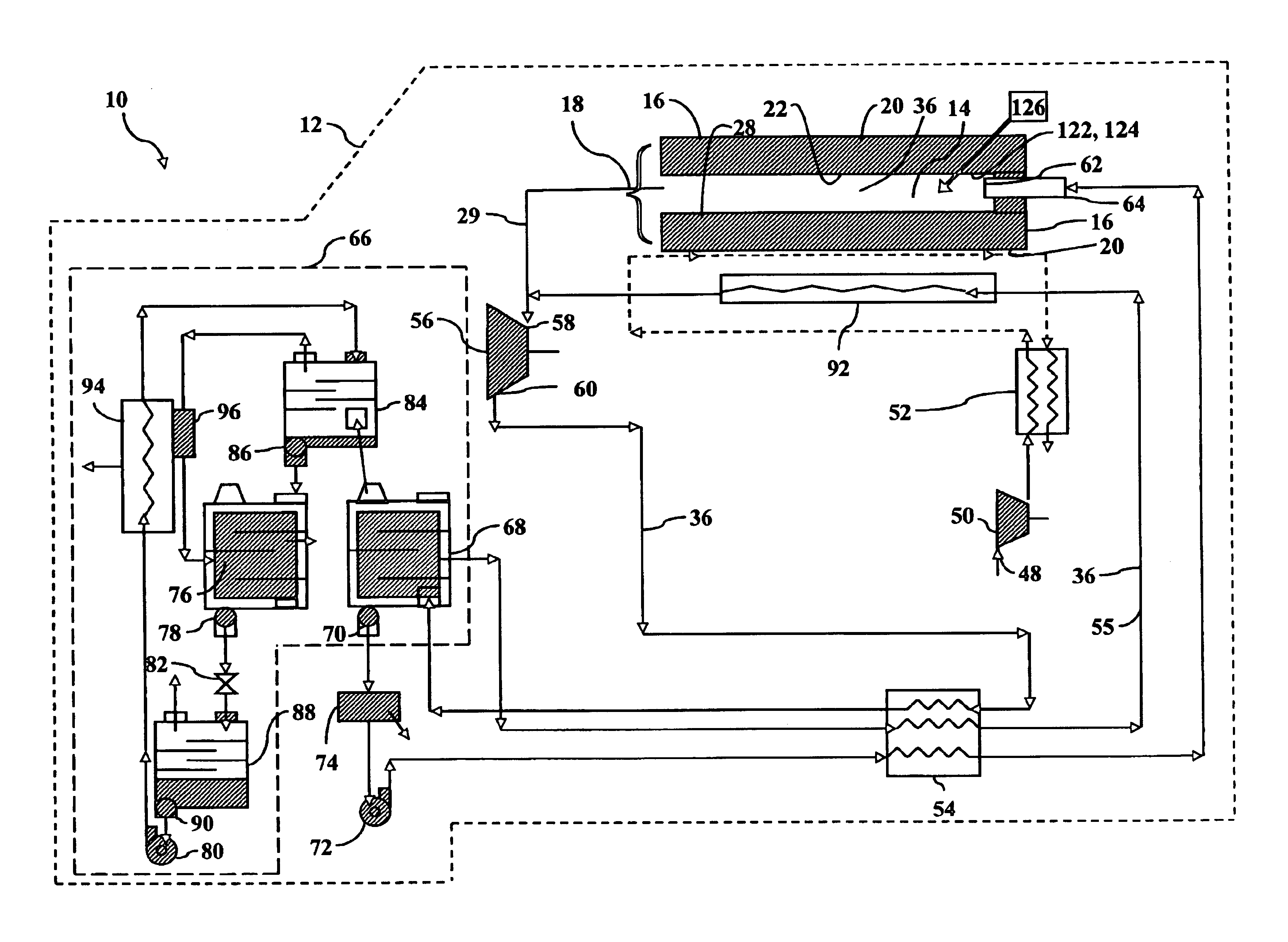
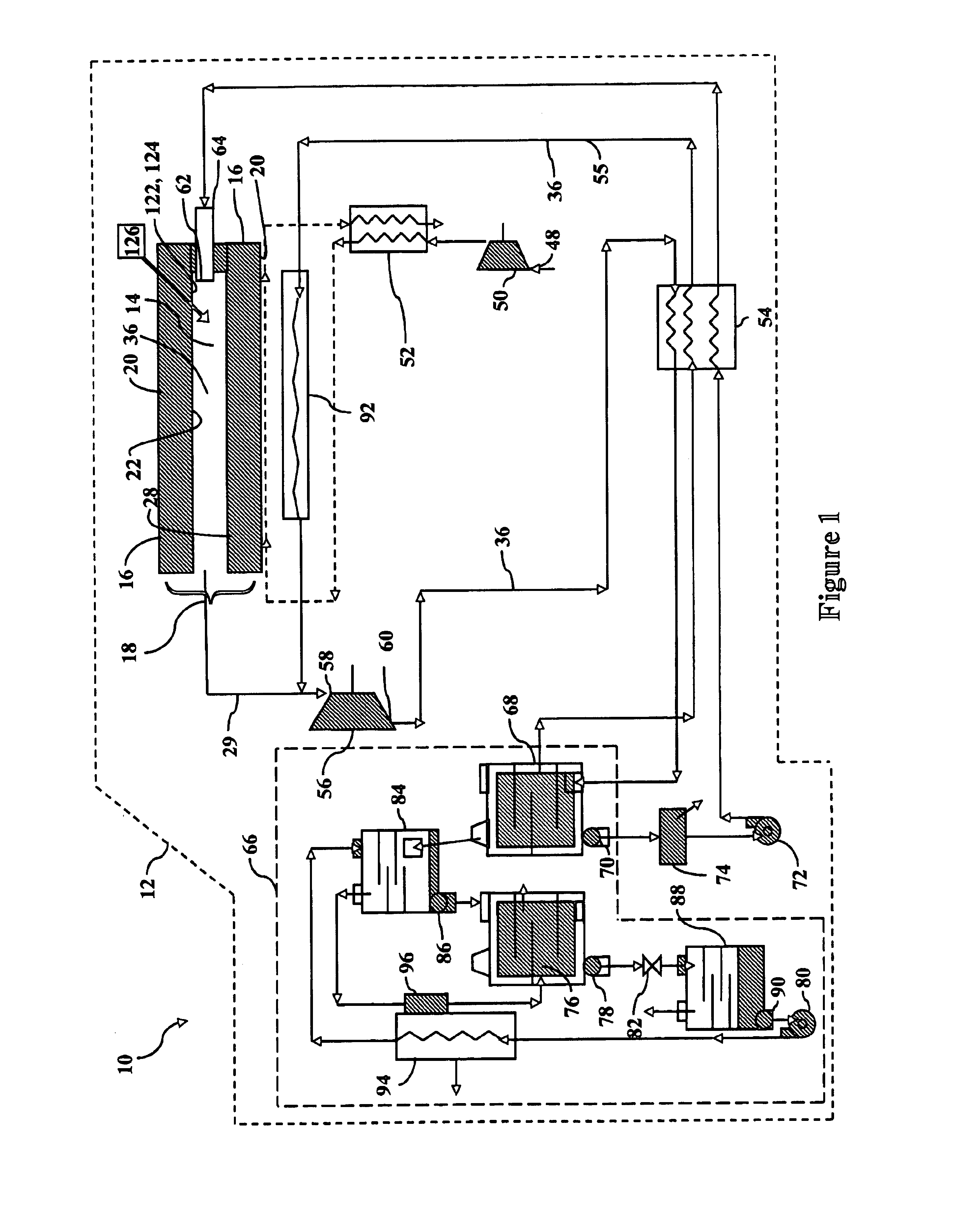
[0044]Referring now to the drawings wherein the showings are for purposes of illustrating preferred embodiments of the present invention only, and not for purposes of limiting the same, FIG. 1 is a schematic diagram of a combustion engine 10 of the present invention illustrating the interconnectivity of components that make up the combustion engine 10. FIG. 1 shows the combustion engine 10 as being comprised of an engine housing 12, an air intake port 48, a mixed conductor 16, a water intake port 62, an exhaust turbine 56 and a hydrogen compressor assembly 66. The engine housing 12 includes a combustion chamber 14 that utilizes a mixed conductor 16 to provide a substantially oxygen-pure fraction of air to the combustion chamber 14 for combustion with hydrocarbon fuel and water and which results in the production of exhaust fluid.

[0045]The combustion engine 10 of the present invention is configured to operate under a process that combusts the hydrocarbon fuel while excluding the prod...


PUM


Abstract

Provided is a combustion engine having a combustion chamber. The combustion engine comprises an engine housing having an air intake port, a mixed conductor, a water intake port, an exhaust turbine and a hydrogen compressor assembly. The air intake port provides air to the mixed conductor which provides an oxygen-pure fraction of air to the combustion chamber by conducting oxygen ions in the air from a retentate side to a permeate side when the oxygen partial pressure on the permeate side is less than that on the retentate side. The water intake port provides water to the combustion chamber for combustion with hydrocarbon fuel and the oxygen-pure fraction of the air to produce exhaust fluid. The exhaust fluid expands in the exhaust turbine causing the turbine rotor to rotate producing mechanical energy. The hydrogen compressor assembly extracts hydrogen from the exhaust fluid and provides hydrogen to the exhaust turbine.

Description

CROSS-REFERENCE TO RELATED APPLICATIONS[0001](Not Applicable)STATEMENT RE: FEDERALLY SPONSORED RESEARCH / DEVELOPMENT[0002](Not Applicable)BACKGROUND OF THE INVENTION[0003]The present invention relates generally to combustion of hydrocarbon fuel and, more particularly, to a combustion engine that extracts hydrogen from exhaust fluid for recirculation through an exhaust turbine. The combustion engine is further configured to combust an oxygen-enriched fraction of air with the hydrocarbon fuel in a manner such that the production of nitrous oxide (NOx) and carbon dioxide (CO2) emissions in the exhaust is reduced or eliminated.[0004]In the operation of a typical combustion engine, heat energy is converted to mechanical energy in order to provide power for transportation, to produce electricity or to operate machinery. Combustion engines may operate in a cycle of repeated sequences of compressing a working fluid to a high pressure, heating the working fluid to a high temperature, then exp...

Claims


Application Information

Patent Timeline
Patent Type & Authority Patents(United States)
IPC IPC(8): F02C3/20F02C3/30F23C99/00F23L7/00
CPCF02C3/30F23C99/00F23L7/002F23L7/007Y02E20/322Y02E20/344Y02E20/34
Inventor CHEN, JEFFREY W.
Owner CHENTEK
Why Eureka
Try Eureka