
Apparatus and method for recording information

a technology of apparatus and information, applied in the field of apparatus and method for recording information, can solve the problems of difficult to form a “loop”, inability to exhibit satisfactory light assist effect, and easy loss of recorded information by thermal decay of magnetization, etc., to achieve efficient heating, simple construction, and high cost

Active Publication Date: 2005-10-04
HITACHI LTD
View PDF3 Cites 13 Cited by
  • Summary
  • Abstract
  • Description
  • Claims
  • Application Information

AI Technical Summary

Benefits of technology

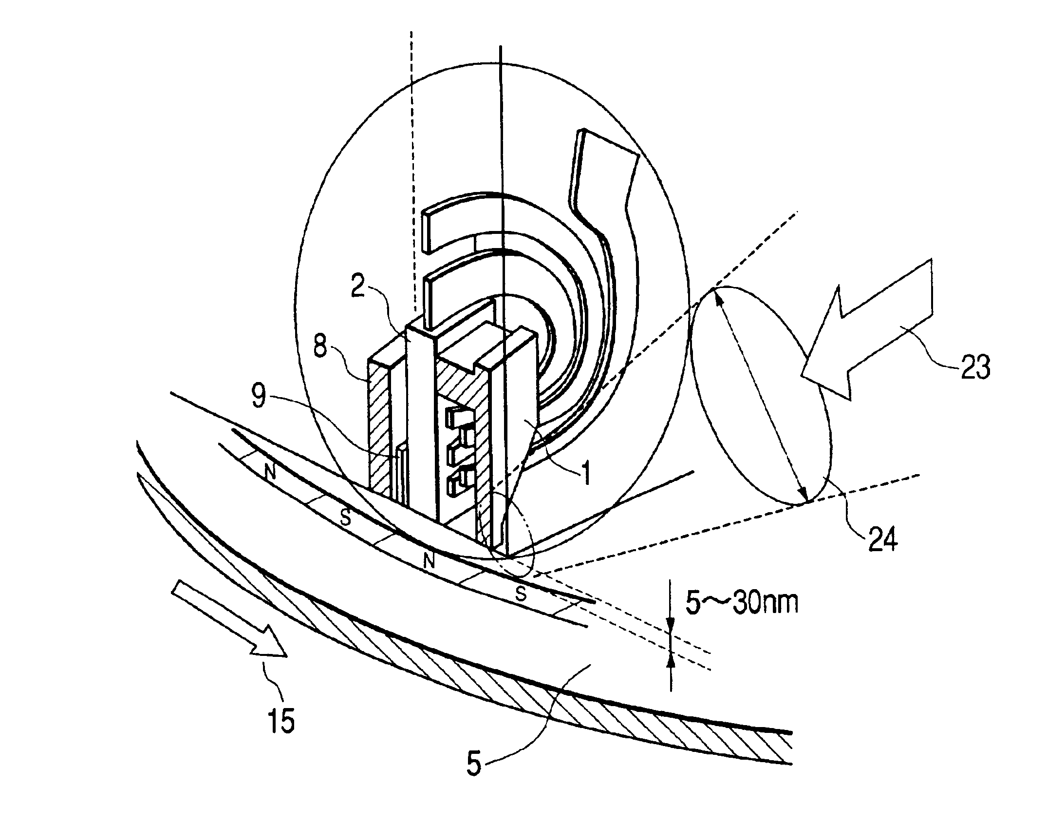
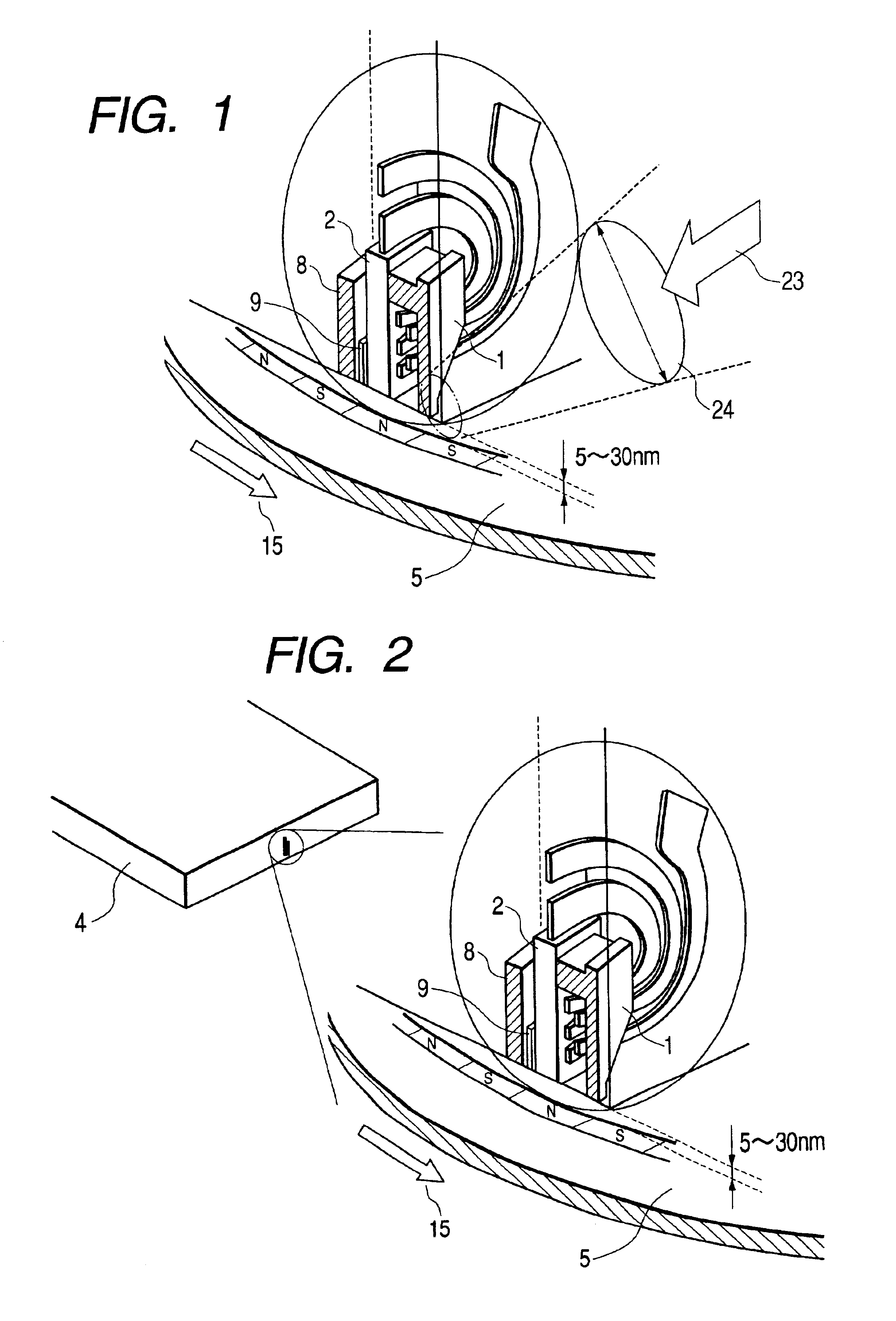
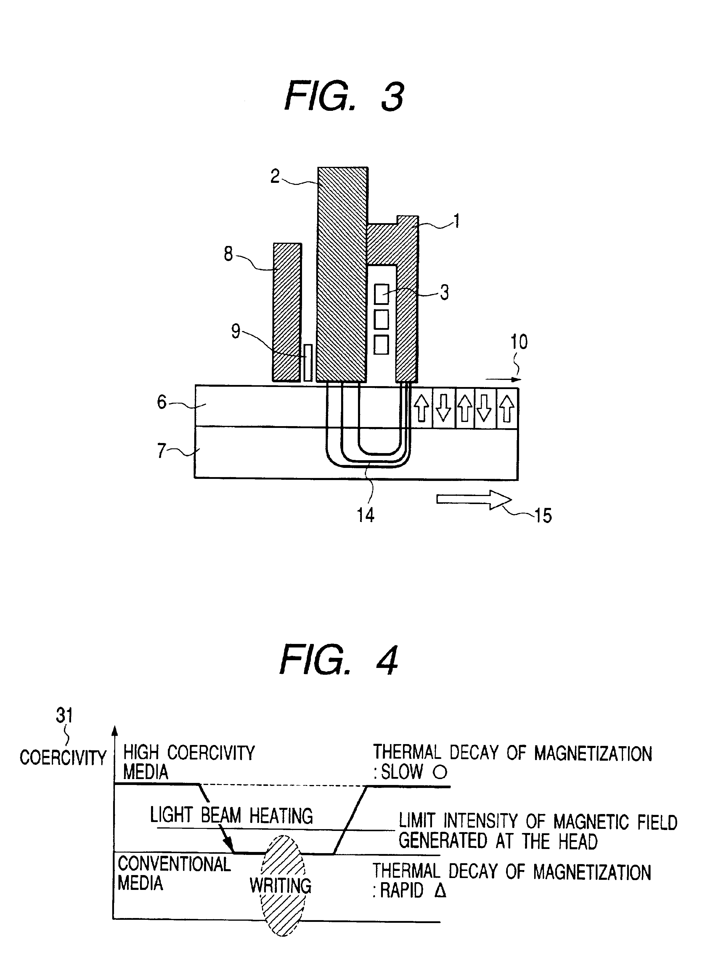
The present invention provides a vertical magnetic recording apparatus that can prevent thermal decay of magnetization and ensure high reliability of information recording life. The apparatus uses a metallic main pole and a metallic recording film in proximity to each other, with a slight gap between them. A light assist method is employed, wherein a light beam is directed to the gap and heats the medium, resulting in a decreased coercivity and increased temperature for writing data. The main technical effects of the invention include reducing the size of the light spot directed to the gap, straddling and covering the main pole, and preventing thermal decay of magnetization.

Problems solved by technology

According to this method, however, recorded information is apt to be lost by thermal decay of magnetization.
Thus, it is difficult to form a “loop” within the film surface, so that stability is maintained easily even against a slight rotation of the recording magnetization based on heat.
There has been the problem that if this light assist method is applied to a conventional vertical recording, a satisfactory light assist effect cannot be exhibited.
Therefore, such pole-to-pole heating as in the intra-surface recording method is inappropriate.
Further, according to the structure adopted in this intra-surface / vertical recording method, light is projected to a narrower gap than the wavelength of light through the use of an elongated waveguide, thus giving rise to the problem that the waveguide efficiency is poor and that a practical quantity of light does not reach a portion of the disk to be irradiated.
In such a low efficiency waveguide structure, it is necessary to use a large-sized laser (such as of several W class) as a light source, and thus, the structure in question is not practical as a small-sized (private use) information terminal.
This apparatus construction is complicated both optically and mechanically, and an actual construction thereof as a hard disk unit results in increased costs.

Method used


Image

  • Apparatus and method for recording information
  • Apparatus and method for recording information
  • Apparatus and method for recording information

Examples


first exemplary embodiment

[0068]In this embodiment, a description will be given below of an apparatus for the supply of light using fiber. An example of a concrete construction of an optical system will be mentioned. FIGS. 11 and 12 show an information recording method and a construction example (Example 1) of an information recording apparatus using a light assist head according to the present invention. FIGS. 11 and 12 are a side view and a perspective view, respectively, of the same apparatus. In FIG. 12, a leaf spring 21 is omitted to make the figure easier to see.

[0069]A basic construction of a magnetic head portion is the same as in FIG. 1. The thin film magnetic head of the vertical recording type referred to earlier is disposed on a disk medium having a metallic, magnetic recording film. In a light condensing system for the incidence of light, a lens 18 obtained by cutting a ball lens into a size of about one fourth, namely, into a “sectorial” shape, is attached to the tip of a slider 4 in the thin f...

second exemplary embodiment

[0079]In the above first embodiment reference has been made to an example of a light supply method using optical fiber. As another example of structure, a description will be given below of an example of structure with an integral laser diode chip. FIG. 14 shows an information recording method and an apparatus construction example (Example 2) using a light assist head according to the present invention.

[0080]The basic construction using the slider 4 and trapezoidal prism 19 in the magnetic head illustrated in FIG. 11 also applies to this embodiment. In this embodiment, however, the trapezoidal prism 19 is shortened, the optical fiber is omitted, and a laser diode chip 30 and wiring for driving the chip replaces the fiber (the provided electric wiring is omitted in the figure). Instead of the external supply of light using optical fiber, the laser diode chip 30 itself is rendered integral on the slider structure, thereby making both optical system and magnetic head integral with each...

third exemplary embodiment

[0082]In the previous embodiments, reference has been made to a construction example on the head side from the leaf spring in the head using the light assist method according to the present invention. Next, with reference to FIGS. 15 and 16, a description will be given below about an entire construction example of a hard disk unit using the light assist method according to the present invention.

[0083]In the hard disk unit shown in FIG. 15, light is fed through an optical fiber to effect light assist. The slider 4 in the thin film magnetic head for vertical recording integral with the trapezoidal prism shown in the first embodiment is attached to the tip of the leaf spring 21, the optical fiber 20 is disposed along the leaf spring 21 and is connected to a semiconductor laser 29 through an optical switch 28, and assist light is fed from the semiconductor laser 29. According to the construction of this embodiment, assist light is fed using an optical fiber 20 as in the first embodiment...


PUM

PropertyMeasurementUnit
oblique angleaaaaaaaaaa
angleaaaaaaaaaa

Abstract

A vertical magnetic recording apparatus is provided which can diminish thermal decay of magnetization to ensure a high reliability of the life of recorded information and which can stably effect the write of magnetic information. Light assist is performed by obliquely applying light to a gap between a main pole of a vertical recording head and a medium. The light is radiated from the head side of the apparatus with respect to the medium. Utilizing the present invention, the thermal decay of magnetization at room temperature is diminished, the life of the recorded information is increased, and the storage reliability of the disk is increased.

Description

CLAIM OF PRIORITY[0001]This application claims priority to Japanese Patent Application No. 2001-259113 filed on Aug. 29, 2001.BACKGROUND OF THE INVENTION[0002]1. Field of the Invention[0003]The present invention relates to a magnetic head for vertical recording involving an optical recording assist, a magnetic disk unit which carries the magnetic head for vertical recording, and information devices and products using the magnetic disk unit.[0004]2. Description of the Background[0005]Along with an increase in the capacity of a hard disk used in computer devices, the information recording density in a single recording surface is also increasing. In a magnetic disk unit, data is read from and written to a recording medium through a magnetic head. In order to increase the recording capacity per unit area of the magnetic disk, the surface recording density must be improved. However, as the recording density increases, the recording area (or “bit size”) occupied by one bit on the recordin...

Claims


Application Information

Patent Timeline
Patent Type & Authority Patents(United States)
IPC IPC(8): G11B5/127G11B5/00G11B5/012G11B5/66G11B13/04G11B13/00G11B5/64G11B5/02G11B5/673G11B11/10
CPCG11B5/00G11B5/012G11B5/127G11B5/1278G11B5/66G11B13/045G11B2005/0002G11B2005/0005G11B2005/001G11B2005/0013G11B2005/0021G11B2005/0029
Inventor ISSHIKI, FUMIOKURODA, ATSUKOICHIHARA, TAKAYUKIMOCHIZUKI, MASAFUMIMATSUMOTO, TAKUYA
Owner HITACHI LTD
Learn More