Catalytic devices and method of making said devices

a technology of catalysts and devices, applied in the direction of physical/chemical process catalysts, lighting and heating apparatus, separation processes, etc., can solve the problems of increasing initial start-up pollution, ineffective reduction of emissions, and too slow catalytic reaction rate for effective treatment of exhaust gas, etc., to achieve faster lightoff and thin catalyst coating

Inactive Publication Date: 2005-10-11
DOW GLOBAL TECH LLC
View PDF39 Cites 38 Cited by
  • Summary
  • Abstract
  • Description
  • Claims
  • Application Information

AI Technical Summary

Benefits of technology

[0012]Surprisingly, the catalytic device of the first aspect may allow the use of a much thinner catalyst coating and faster lightoff than the typical automobile catalytic converter. In addition, the catalytic device may also be used as a filter element for entrapping soot particles that are subsequently burned off by the heat generated by the catalytic exothermic reactions of the catalytic device (e.g., CO+½O2=CO2).

Problems solved by technology

Even though these catalytic converters are effective in reducing emissions once they reach operating temperatures, they are not very effective at reducing emissions upon “cold start.” Cold start is when the catalyst temperature is low (e.g., ambient) and the rate of catalytic reaction is too slow for effective treatment of exhaust gas.
Considering the amount of automobiles and ever more stringent clean air standards, this initial start-up pollution has become more of a problem.
This approach suffers from excessive wear on the battery, added complexity and inability to start the vehicle and go immediately (i.e., it takes a couple of minutes for the converter to warm up).
This approach also suffers from added complexity, the inability to start and go immediately and limited time where the heat may be retained (e.g., 24 hours or less).

Method used


Image

  • Catalytic devices and method of making said devices
  • Catalytic devices and method of making said devices
  • Catalytic devices and method of making said devices

Examples


example 1

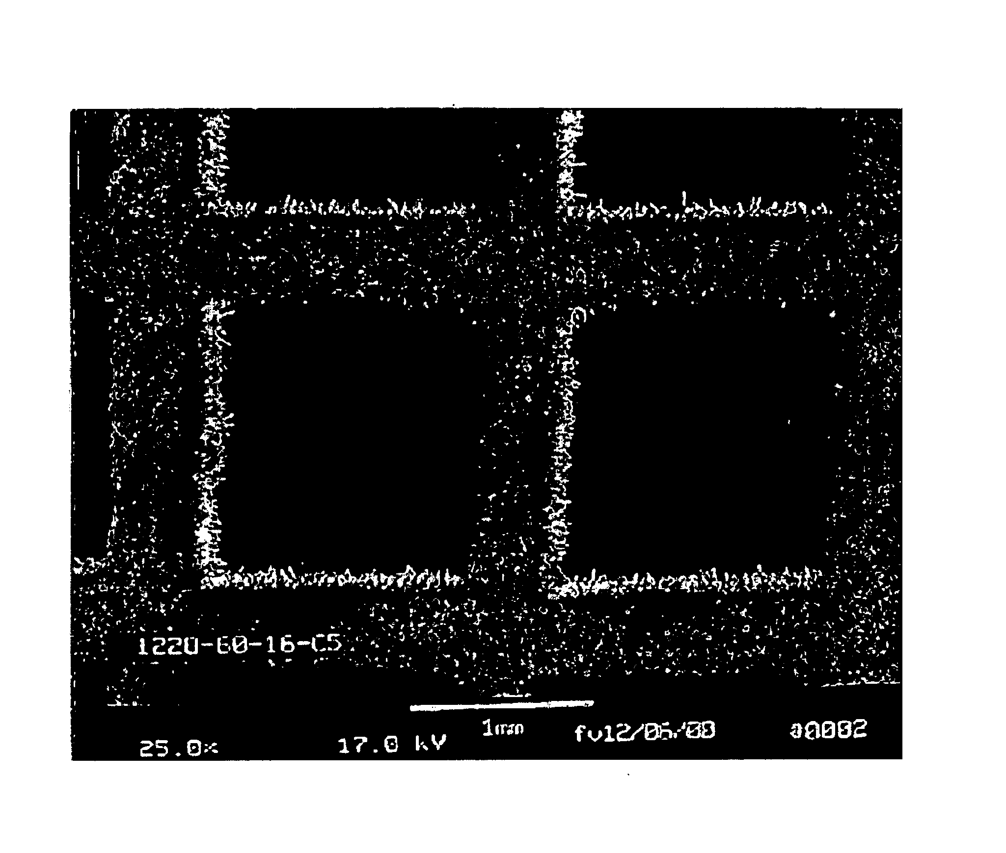
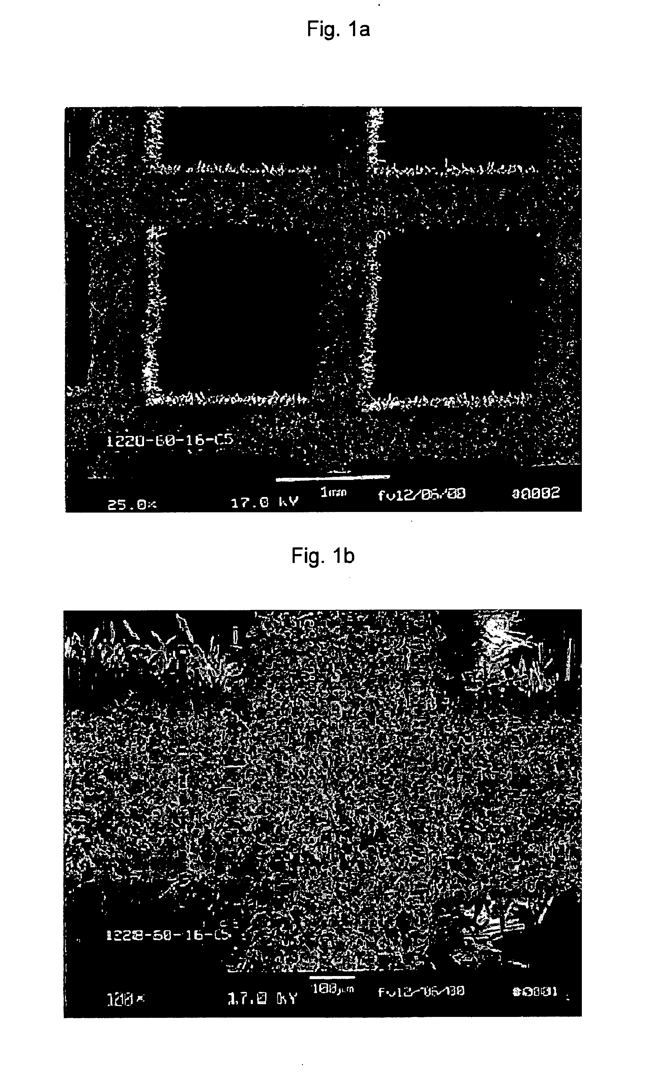
[0057]Square channel honeycombs having a cell density of about 240 cells per square inch and a wall thickness of about 0.013 to 0.014 inch were formed by extruding a mixture of natural ball clay (Todd Dark grade, Kentucky-Tennessee Clay Company), κ-alumina (ALCOA gibbsite calcined at 1100° C.) and polymer binders. The clay and alumina were mixed in proportions to give an Al:Si atom ratio of 3.15. A honeycomb was extruded. The extruded honeycomb was then slowly heated in air up to 1000° C. for one hour in order to burn off the polymeric binder and drive off the clay's structural water. The resulting calcined honeycomb was cut to the size required for testing and then converted to acicular mullite in a vacuum furnace attached to a SiF4 source and equipped to allow control of the gas atmosphere.

[0058]The calcined honeycomb was heated under vacuum to 735° C. and held at that temperature for at least one hour, then cooled under vacuum to about 720° C. At this point, SiF4 gas was added to...

example 2

[0062]Example 2 was prepared and tested in the same way as Example 1, except that the platinum concentration was 1.56 grams per liter and the light-off temperature was 233° C. and extinction temperature of 200° C. (also shown in Table 1).

example 3

[0063]Example 3 was prepared and tested in the same way as Example 1, except that the aqueous solution of diaminedinitritoplatinum concentration was 0.85 percent by weight thereof, the concentration of platinum was 2.03 grams per liter and the light-off temperature was 224° C. and extinction temperature of 185° C. (also shown in Table 1).


PUM

PropertyMeasurementUnit
box sizeaaaaaaaaaa
box sizeaaaaaaaaaa
aspect ratioaaaaaaaaaa

Abstract

The invention is a catalytic device comprised of a catalyst support of fused ceramic grains and a catalyst that is surface-bound to at least a portion of the ceramic grains, incorporated into at least a portion of the ceramic grains or combinations thereof, wherein the grains and catalyst form a surface structure that has a box counting dimension of greater than 1.00 or the box counting dimension has at least one step change when measured from a box size “d” of at least about 1 micrometer to at most about 1 millimeter. The invention is particularly useful in making a catalytic converter or catalytic converter-soot trap.

Description

CROSS-REFERENCE TO RELATED APPLICATION[0001]This application claims the benefit of U.S. Provisional Application Ser. No. 60 / 173,017, filed Dec. 23, 1999.FIELD OF THE INVENTION[0002]The invention relates to catalytic converters for automotive and diesel applications.BACKGROUND OF THE INVENTION[0003]Catalytic converters were first used in the early 1970s to reduce harmful exhaust emissions, such as carbon monoxide, hydrocarbons and nitrous oxides (NOx) produced by automobiles. These converters are still employed and are typically made by forming a honeycomb support structure comprised of metal or ceramic (e.g., cordierite) covered by a coating containing a precious metal catalyst. The catalyst-coated structure is placed in a metal container connected to the exhaust system, such that the exhaust gas flows through the channels of the honeycomb.[0004]The catalyst coating is typically applied using a wash coat consisting of nanometer size particles of precious metal (e.g., platinum, palla...

Claims


Application Information

Patent Timeline
Patent Type & Authority Patents(United States)
IPC IPC(8): B01D53/94B01J35/04B01J35/00F01N3/10B01D53/86B01J21/16B01J23/40B01J23/42B01J35/02B01J37/00B01J37/02
CPCB01D53/945B01J21/16B01J35/023B01J35/04B01J23/40B01J37/0009B01J37/0215F01N2330/06Y02C20/10Y02T10/22Y02T10/12Y02A50/20B01D53/94
Inventor WALLIN, STEN A.CHRISTENSON, CHRISTOPHER P.WEST, DAVID H.CORNELL, MARTIN C.JOVANOVIC, ZORAN R.GRUENBAUER, HENRI J. M.
Owner DOW GLOBAL TECH LLC
Why Eureka
Try Eureka