Non-invasive, miniature, breath monitoring apparatus

a breath monitoring and miniature technology, applied in the field of breath monitoring apparatus, can solve the problems of slow instrument development and achieve the effects of low maintenance requirements, low sample volume and low cos

Inactive Publication Date: 2005-10-18
OAK CREST INST OF SCI
View PDF15 Cites 44 Cited by
  • Summary
  • Abstract
  • Description
  • Claims
  • Application Information

AI Technical Summary

Benefits of technology

[0049]The purpose of the present invention is to provide a non-invasive, miniature breath monitoring device or system that can be used as an effective medical diagnostic tool. The non-invasive, miniature breath monitoring device system disclosed herein utilizes an analyzer that is unique by virtue of a simultaneous and continuous measurement of C2H2, CO2, and SF6 in a gaseous matrix in one low-cost, miniature device approximately the size of a shoe box. The analyzer response is linear over full-scale ranges of 1.0–2.0%v, for C2H2 and SF6; 10%v for CO2. A full-scale reading of 20% O2 is an optional add-on feature. The analyzer detection limits (2σ) are 2% of full-scale, or better, with a 10–50 msec. response time (10–90%); accuracy is typically ±2% of full-scale, or better. The rapid response time of the analyzer also distinguishes it from other gas analyzes used in the art. Unlike other IR C2H2 monitors, it does not suffer from cross-interferences, notably from H2O vapor. The instrument has a low sample volume (preferably less than 1.25 mL) and requires low power input (less than 50 watts during warm up, less than 25 watts during steady state). It is suitable for telemetry and is rugged with very low maintenance requirements.

Problems solved by technology

Breath analysis as a non-invasive means of medical diagnostics has been touted for many years but the evolution of suitable instruments has been slow.

Method used


Image

  • Non-invasive, miniature, breath monitoring apparatus
  • Non-invasive, miniature, breath monitoring apparatus
  • Non-invasive, miniature, breath monitoring apparatus

Examples


Embodiment Construction

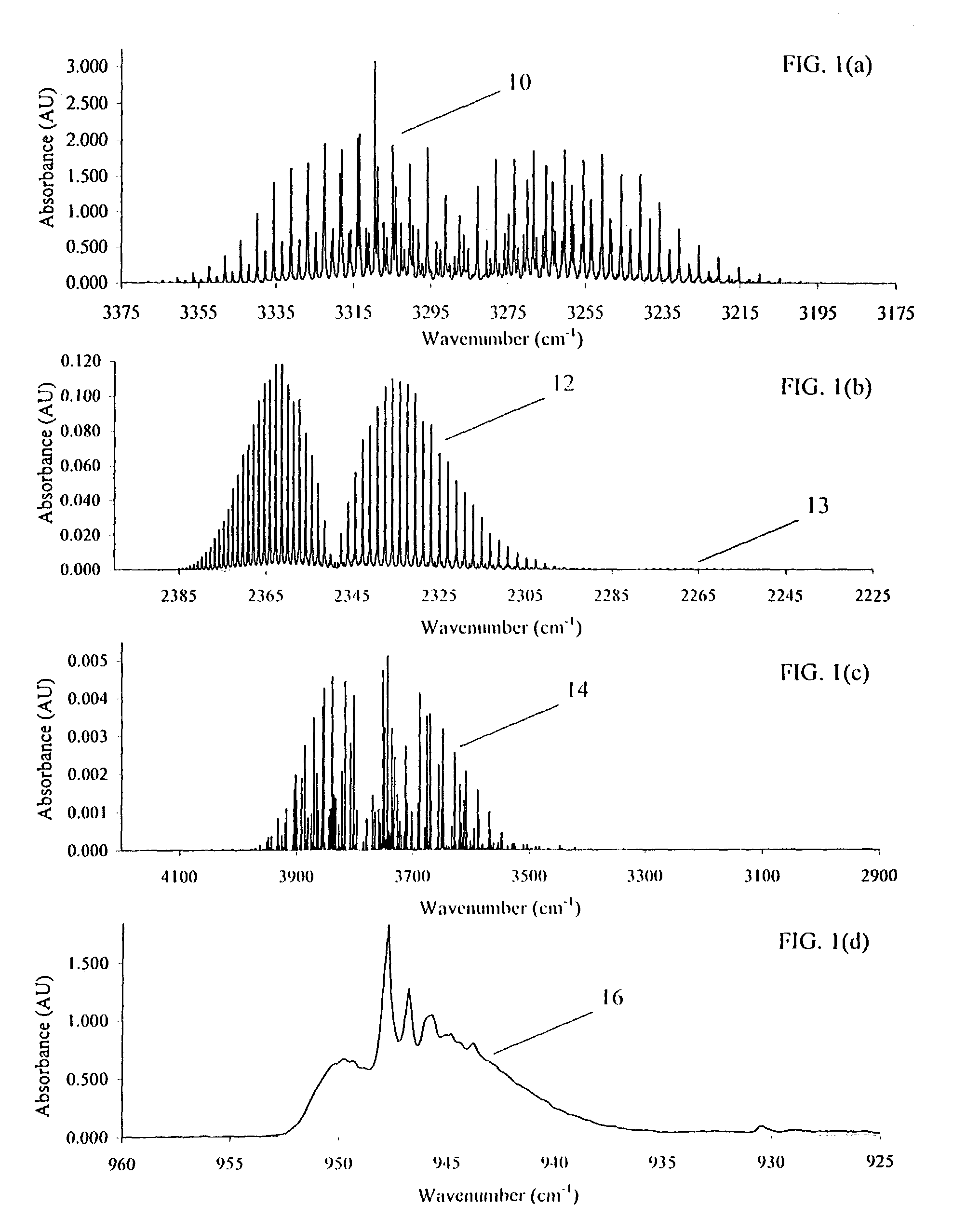
[0089]The stacked IR Spectra of analytes commonly measured by the invention disclosed herein are illustrated in the graphs of FIGS. 1(a) through 1(d). FIG. 1(a) illustrates the spectra for acetylene (C2H2); FIG. 1(b) is the spectra of carbon dioxide (CO2) 12; FIG. 1(c) is the spectra of an analyte of water 14 (H2O); and FIG. 1(d) is a spectra of sulfur hexafluoride (SF6) 16.

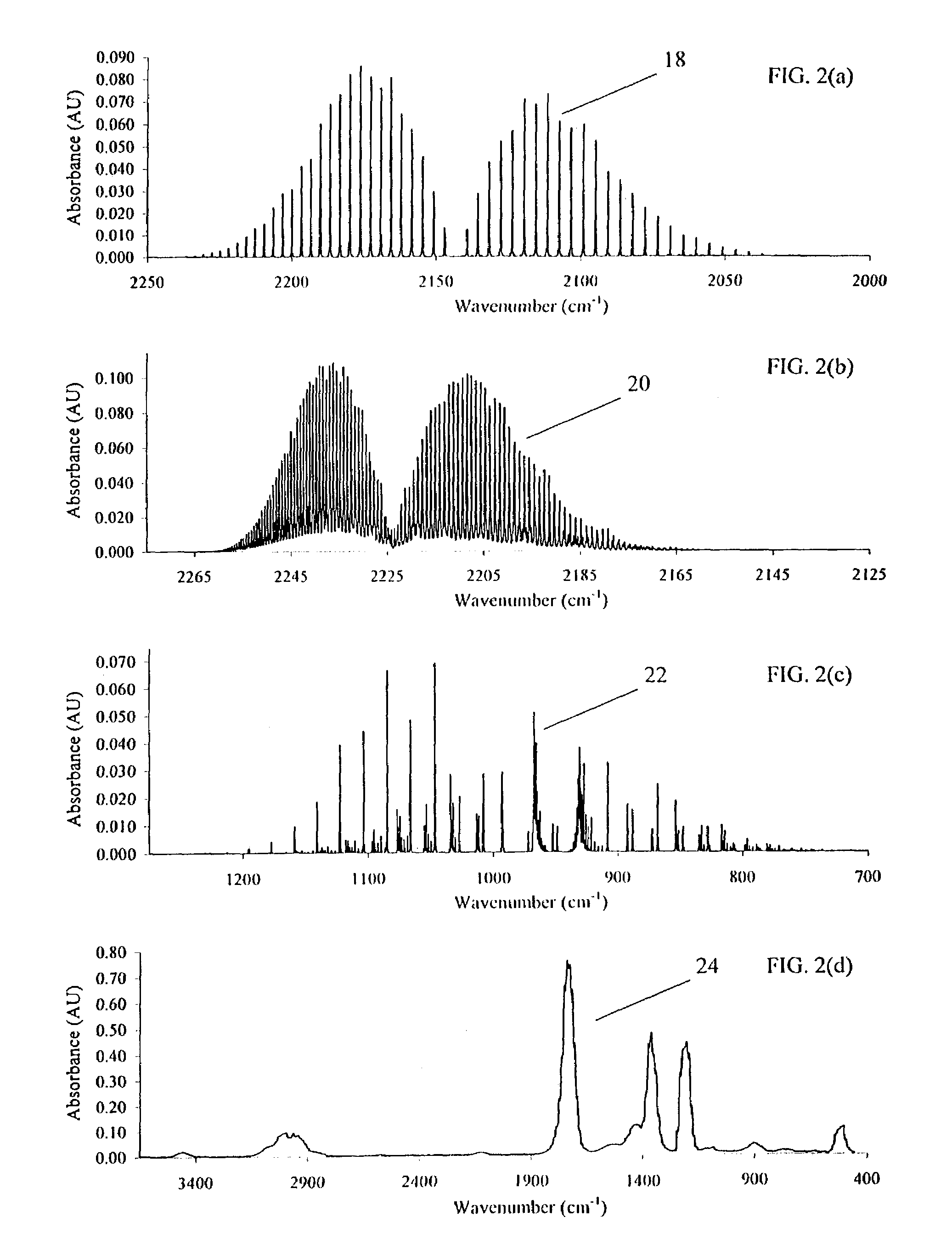
[0090]FIGS. 2(a) through 2(d) are graphs of stacked IR spectra of additional analytes of interest to breath analysis that can be measured by the invention disclosed herein. FIG. 2(a) is the spectra of carbon monoxide (CO) 18; FIG. 2(b) is the spectra of nitrous oxide (N2O) 20; FIG. 2(c) is the spectra of ammonia (NH3) 22; FIG. 2(d) is the spectra of acetone 24. Each of the analytes of these spectra can be measured by the analyzer of the present invention.

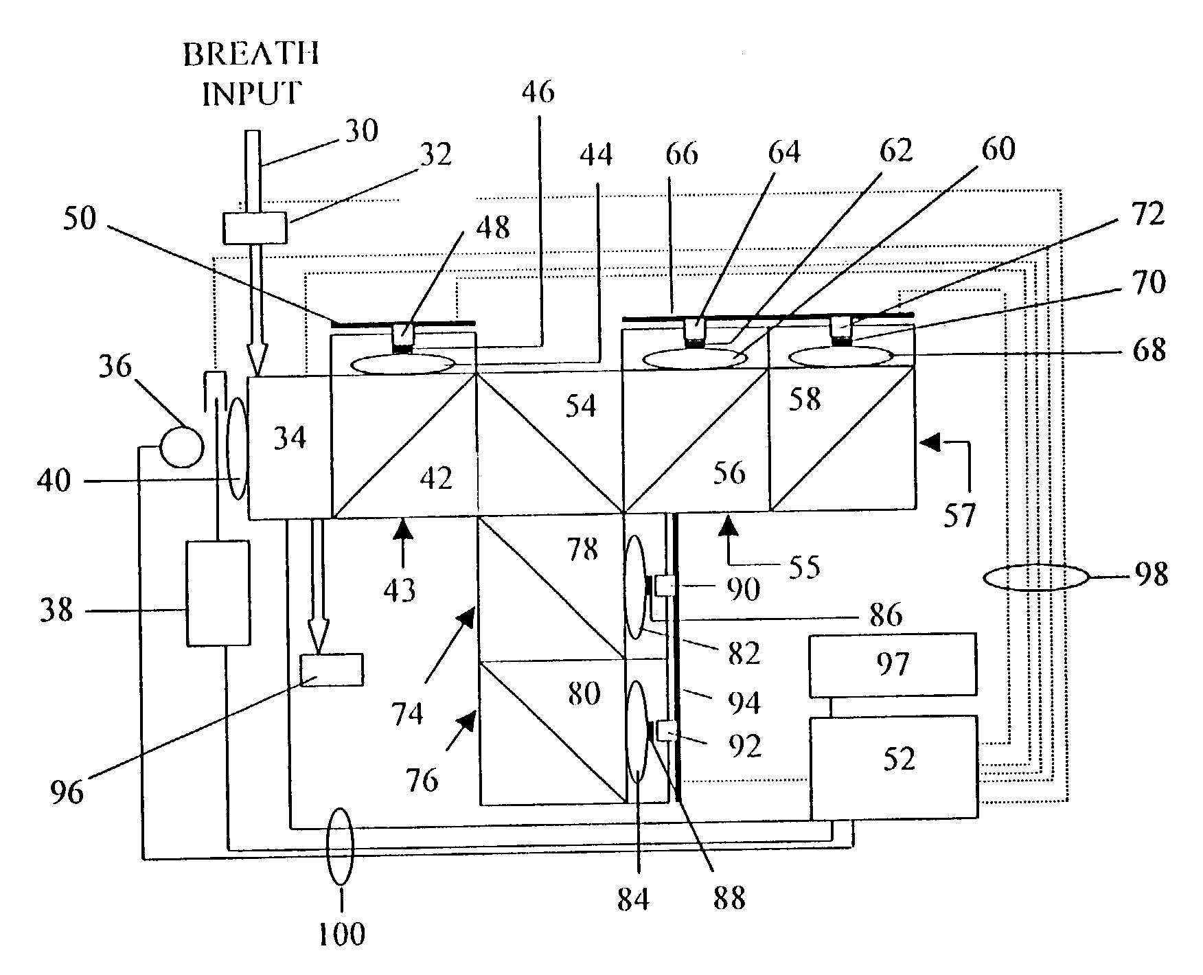
[0091]A preferred embodiment of the present invention is illustrated in the schematic block diagram of FIG. 3. The subject or patient breathes into an apparatus ...


PUM

PropertyMeasurementUnit
response timeaaaaaaaaaa
volumeaaaaaaaaaa

Abstract

A rugged, miniature, spectroscopic gas analyzer apparatus for rapid, non-invasive, multi-component breath monitoring and analysis and subsequent determination of Q or other medical diagnostic applications. The system is comprised of one or more IR emitters focussed by optical elements through a low volume sample cell receiving a sample input of a patient's breath for analysis. The patient either at rest or during exercise, inhales C2H2—SF6 mixtures (balance of oxygen and nitrogen) which is subsequently monitored upon exhalation for CO2, H2O, C2H2, and SF6 which can be employed to determine Q directly and accurately. Measurements are performed in real-time or via post-processing of stored original data. Due to its small size, ruggedness, and low power consumption, the monitor can conveniently be employed in the field or data can also be retrieved remotely using telemetry. The miniature analyzer operates on the principle of infrared absorption spectroscopy and allows very precise concentration measurements of the analytes of interest, without any bias or interference from other matrix components.

Description

[0001]This application is a Divisional of application Ser. No. 09 / 891,106 filed Jun. 25, 2001 now U.S. Pat. No. 6,599,253.BACKGROUND OF THE INVENTION[0002]1. Field of the Invention[0003]This invention relates to a breath monitoring apparatus for diagnostic purposes and more particularly relates to a miniature spectroscopic gas analyzer for patient breath analysis to determine cardiac output (Q).[0004]2. Background Information[0005]The determination of Q—the amount of blood pumped by the heart per minute—at rest or during exercise is a powerful diagnostic tool for assessing patient health. Currently, the state of diagnostic technology is hospital and research-center based and features expensive, sensitive equipment.[0006]A series of invasive and non-invasive techniques have been developed for Q monitoring during rest and submaximal exercise. The “gold” standard generally is considered to be the dye-dilution method, with thermodilution a close second. Both methods are invasive and mea...

Claims


Application Information

Patent Timeline
Patent Type & Authority Patents(United States)
IPC IPC(8): A61B5/083A61B5/08G01N33/483G01N21/05G01N21/31G01N21/03G01N21/35G01N33/497A61B5/026A61B5/00A61B5/029G01N21/39
CPCA61B5/0813A61B5/083G01N21/05G01N21/3504G01N33/497A61B5/0059A61B5/029G01N2021/3129G01N2021/3137G01N2021/3166G01N2021/398
Inventor BAUM, MARC M.LORD, HARRY C.
Owner OAK CREST INST OF SCI
Why Eureka
Try Eureka