Lithographic apparatus, device manufacturing method, and device manufactured thereby

a technology of lithographic projection and manufacturing method, which is applied in the direction of printers, duplicating/marking methods, decorative arts, etc., can solve the problems of increasing the amount of space required for alignment markers on the substrate, and not being available for device production, so as to improve the capture range, improve the accuracy, and improve the effect of positioning information

Inactive Publication Date: 2005-11-01
ASML NETHERLANDS BV
View PDF4 Cites 668 Cited by
  • Summary
  • Abstract
  • Description
  • Claims
  • Application Information

AI Technical Summary

Benefits of technology

[0017]By detecting intensity in the pupil plane, the alignment system makes maximum use of the available information. For example, by detecting intensity variations at the positions of a plurality of diffraction orders in the pupil plane, extremely fine positioning information can be derived. This information is obtained from the relative phases in the intensity variations as the marker is scanned; the different diffraction orders will vary in intensity with different spatial frequencies. A central alignment position can be determined when several intensity peaks coincide. Alternatively, or in addition, by measuring intensity at two positions closely spaced on opposite sides of a diffraction order, a coarse position, or capture, can be obtained by detecting beat frequencies between the two intensity signals. The size of the capture range is determined by the spacing of the detectors—the closer the detectors, the larger the capture range. Furthermore, by detecting phase variations in dark areas of the pupil plane, asymmetries in the marker can be detected and used to compensate for errors in the alignment position caused by such asymmetries.
[0018]The alignment system of the present invention has particular advantages in that it can be used with various different forms of marker, including those known in the prior art, providing valuable backwards compatibility. The alignment system of the present invention can also be made directly compatible with prior art alignment systems, allowing end users to make use, without modification, of marker arrangements and processes derived for earlier systems. Further, the alignment system can provide additional features and more accurate alignment.
[0019]The present invention can also use new alignment markers, having higher spatial frequencies than the prior art, providing improved robustness and accuracy of alignment. Additionally, a single frequency short grating can be used reducing the amount of scribe lane real estate devoted to alignment markers.
[0020]In embodiments of the invention, an unfiltered camera image of the marker can be provided. This image will be sharper and can be used for additional functions, such as capturing.
[0021]The present invention can also be embodied in a modular form where the front part has strict stability requirements and a back part has less strict stability requirements. The back part can be modified and upgraded without the need to change the front end.

Problems solved by technology

However, the need to provide two gratings with different periods increases the amount of space required for the alignment markers on the substrate.
It is desirable to minimize the amount of such “silicon real estate” devoted to alignment marks and therefore not available for production of devices.

Method used


Image

  • Lithographic apparatus, device manufacturing method, and device manufactured thereby
  • Lithographic apparatus, device manufacturing method, and device manufactured thereby
  • Lithographic apparatus, device manufacturing method, and device manufactured thereby

Examples


Embodiment Construction

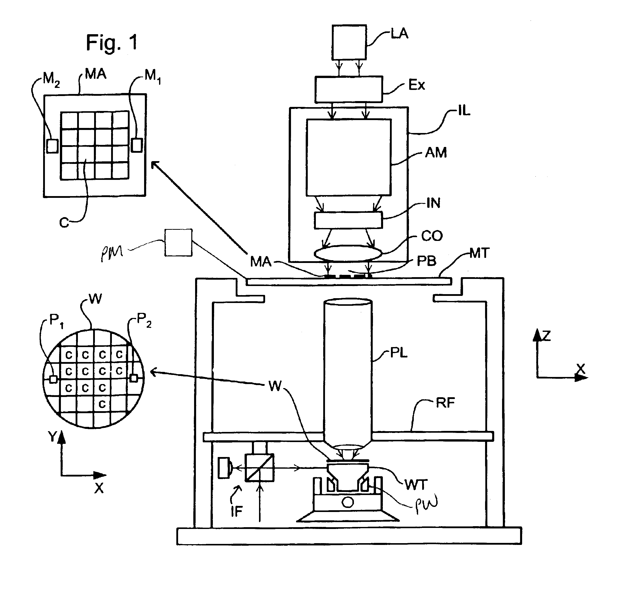
[0058]FIG. 1 schematically depicts a lithographic projection apparatus 1 according to an embodiment of the invention. The apparatus includes a radiation system Ex, IL constructed and arranged to supply a beam PB of radiation (e.g. UV or EUV radiation, such as, for example, generated by an excimer laser operating at a wavelength of 248 nm, 193 nm or 157 nm, or by a laser-fired plasma source operating at 13.6 nm). In this embodiment, the radiation system also comprises a radiation source LA. The apparatus also includes a first object (mask) table MT provided with a mask holder constructed and arranged to hold a mask MA (e.g. a reticle), and connected to a first positioning device PM to accurately position the mask with respect to a projection system or lens PL; a second object (substrate) table WT provided with a substrate holder constructed and arranged to hold a substrate W (e.g. a resist-coated silicon wafer) and connected to a second positioning device PW to accurately position th...


PUM

PropertyMeasurementUnit
wavelengthaaaaaaaaaa

Abstract

An alignment system uses a self-referencing interferometer that produces two overlapping and relatively rotated images of an alignment markers. Detectors detect intensities in a pupil plane where Fourier transforms of the images are caused to interfere. The positional information is derived from the phase difference between diffraction orders of the two images which manifests as intensity variations in the interfered orders. Asymmetry can also be measured by measuring intensities at two positions either side of a diffraction order.

Description

RELATED APPLICATION[0001]This application claims the benefit of priority to European Application No. 02254057.9, filed Jun. 11, 2002, the contents of which are herein incorporation by reference.BACKGROUND OF THE INVENTION[0002]1. Field of the Invention[0003]The present invention relates to a lithographic projection apparatus, a device manufacturing method, and a device manufactured thereby.[0004]2. Description of the Related Art[0005]The term “patterning device” as here employed should be broadly interpreted as referring to device that can be used to endow an incoming radiation beam with a patterned cross-section, corresponding to a pattern that is to be created in a target portion of the substrate. The term “light valve” can also be used in this context. Generally, the pattern will correspond to a particular functional layer in a device being created in the target portion, such as on integrated circuit or other device (see below). An example of such a patterning device is a mask. T...

Claims


Application Information

Patent Timeline
Patent Type & Authority Patents(United States)
IPC IPC(8): G03F9/00G01B9/02G01B11/00H01L21/027
CPCG03B27/32G03F9/7049G03F9/7088G03F9/7076Y10T428/24802H01L21/027
Inventor DEN BOEF, ARIE JEFFREYHOOGERLAND, MAARTENGAJDECZKO, BOGUSLAW
Owner ASML NETHERLANDS BV
Why Eureka
Try Eureka