Oxidizing undesired compounds resident within liquid absorbent compounds, reducing atmospheric pollution, regenerating a liquid absorbent and conserving fuel usage associated with reboiler utilization

a technology of liquid absorbent compounds and oxidizing undesired compounds, which is applied in the direction of liquid degasification, combustion types, separation processes, etc., and can solve problems such as liquid surges

Inactive Publication Date: 2005-11-15
KHOSROWYAR PARVIZ
View PDF26 Cites 11 Cited by
  • Summary
  • Abstract
  • Description
  • Claims
  • Application Information

AI Technical Summary

Benefits of technology

[0019]The present invention provides an apparatus and process which near completely oxidizes effluents comprised of undesirable combustible vapors and ambient condensed liquid. There are no residuals to dispose of, or intermediate separators and pumps to contend with. The controlled oxidizing chamber of the present invention oxidizer via temperature and forced draft burner controls ensures oxidation of effluents at a 99.0+% efficiency.
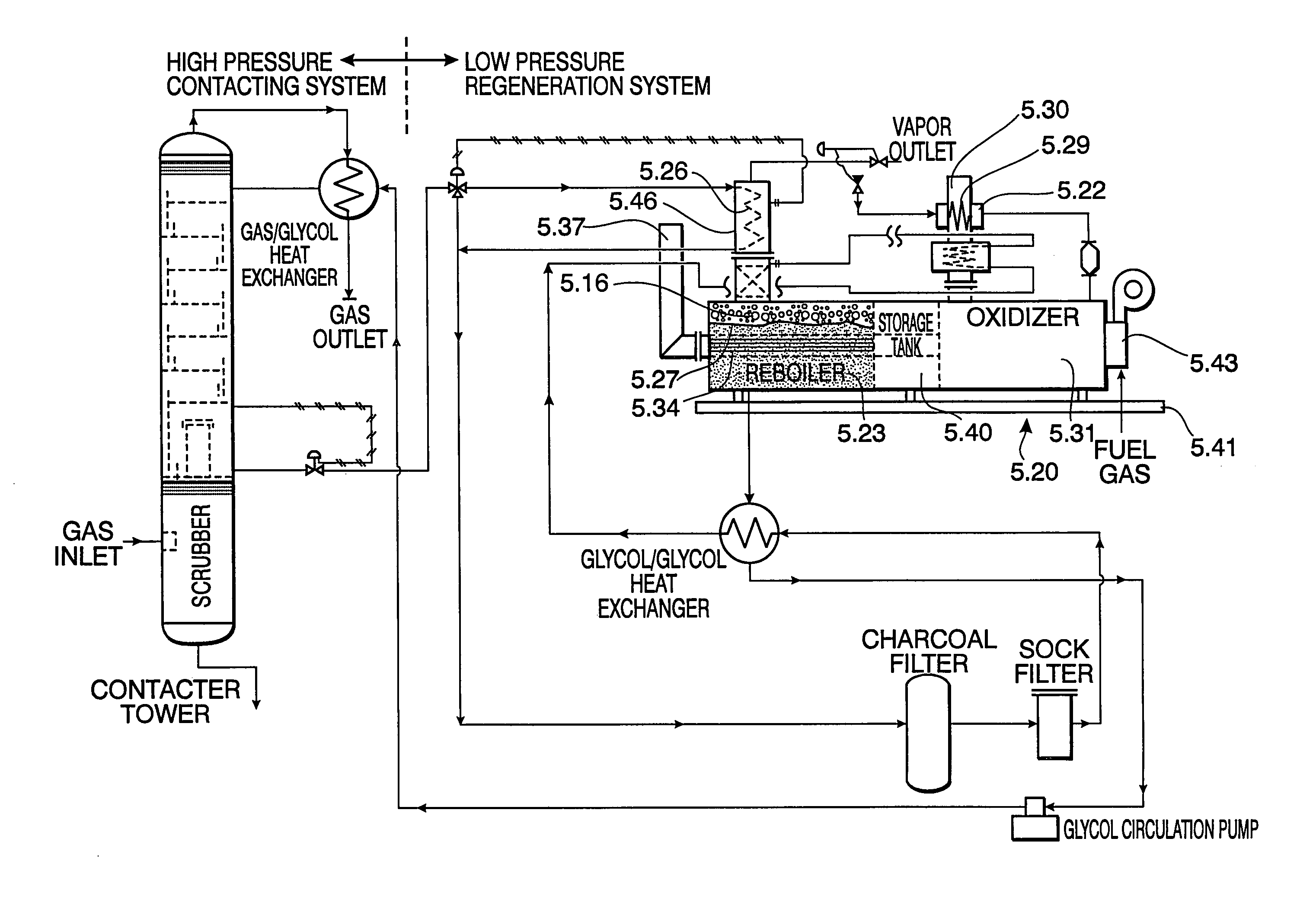
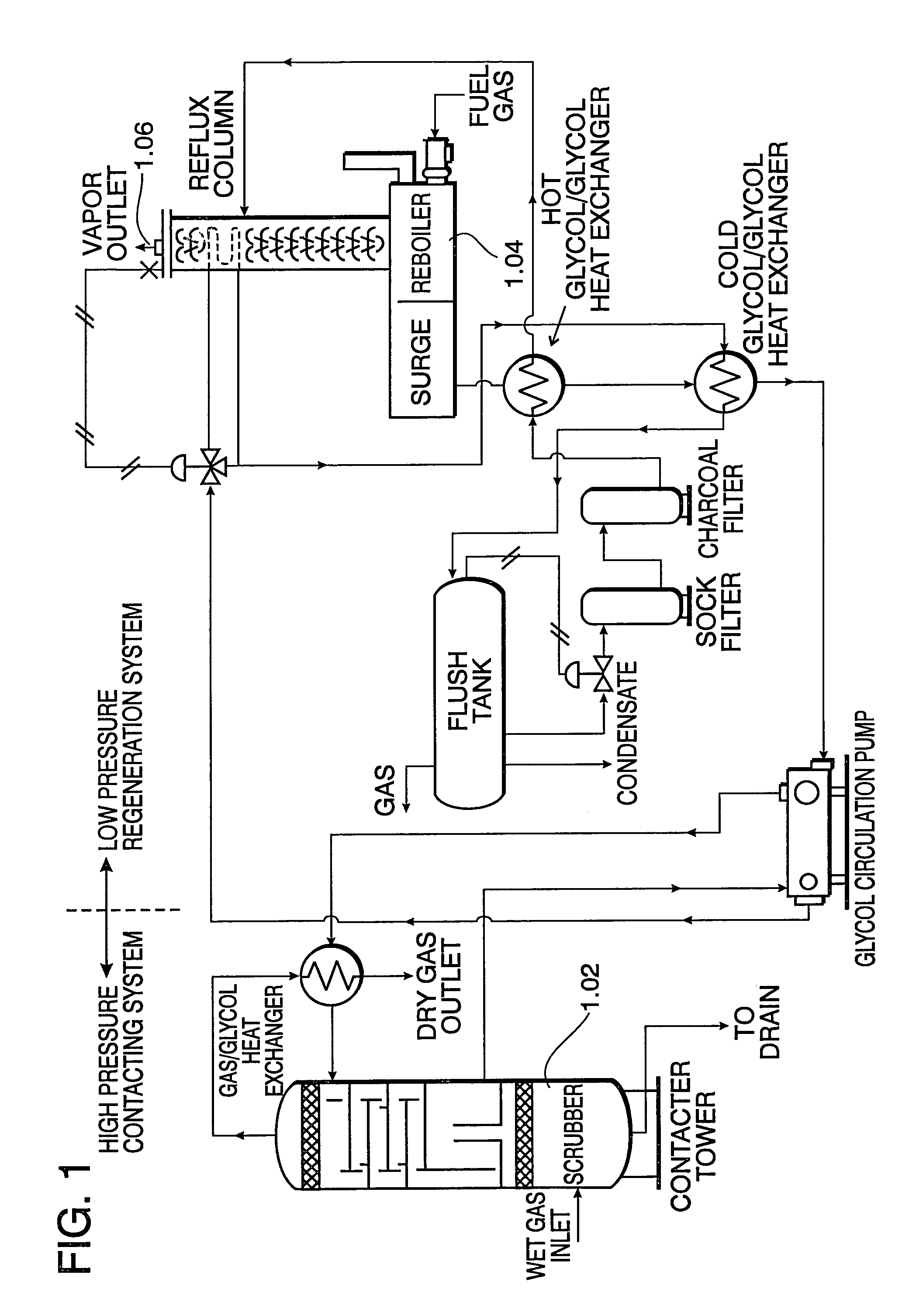
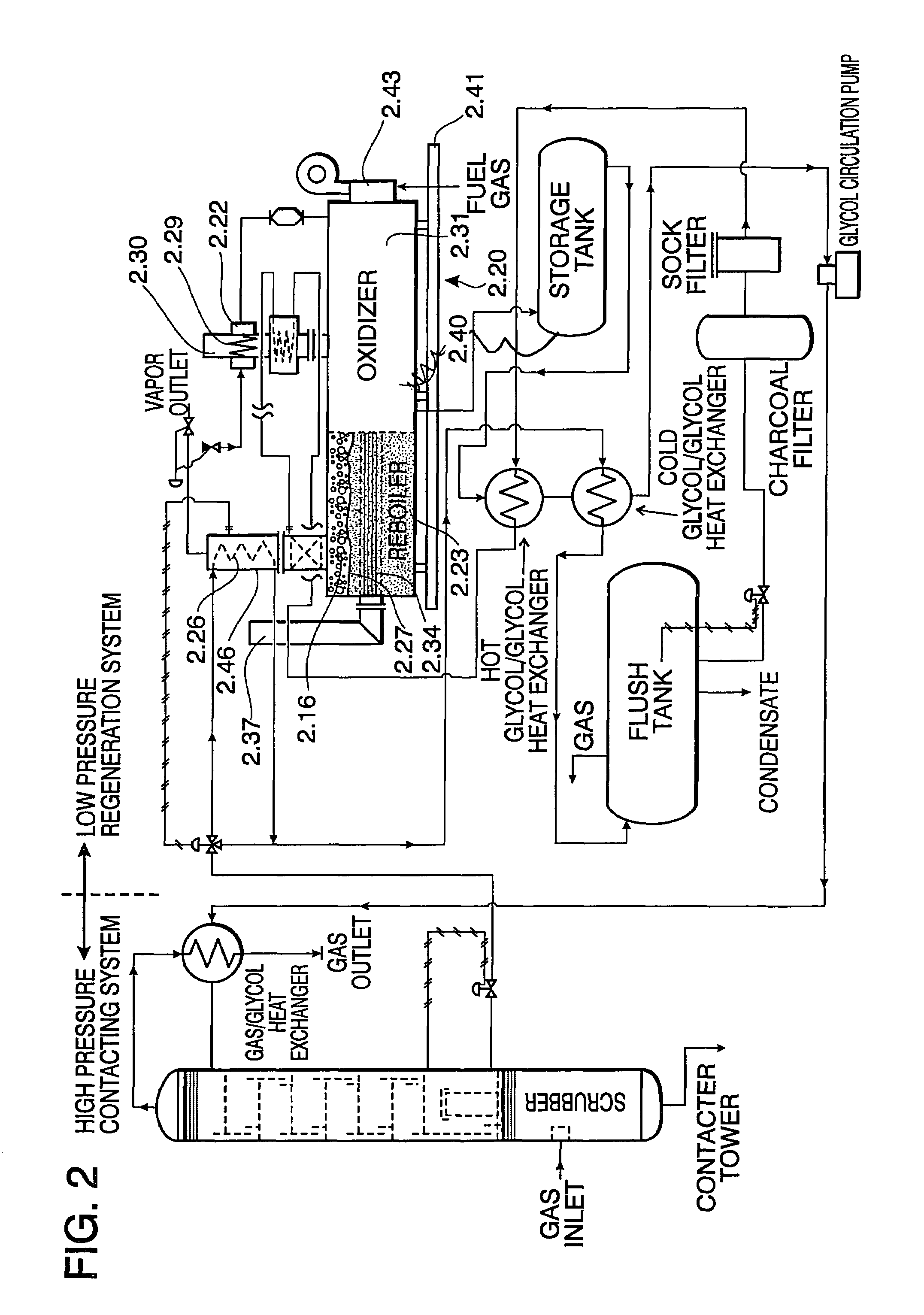
[0020]The present invention is directed to an improved method and apparatus for oxidizing undesired compounds residing within a liquid glycol based natural gas processing system. Vaporized effluents exiting a reboiler chamber contain a certain amount of benzene, toluene and other volatile organic compounds (VOC's). Prior to entering the thermal oxidizer chamber of the instant invention, vapor outflow from a still column, which may be embodied as a reflux column, connected to the reboiler chamber is passed into and through a vaporizing heat exchanger which serves to revaporize any liquid in the outflow from the still / reflux column. By reducing the liquid inflow to the oxidizing chamber of the instant invention (or retaining the vapor form) oxidation is enhanced. A second feature of the heat exchanger is that it will contain a reservoir to contain any surges of liquid. Notwithstanding the fact that outflow from the still / reflux column should contain only water vapor and hydrocarbons, there are occasionally surges of liquid as the outflow from the vapor outlet is not steady state, but constantly changing. Once the vapor has passed through the vaporizing heat exchanger, it is directed to an inlet of the invention's thermal oxidizer combustion chamber. The oxidizer chamber contains a burner and also contains sufficient insulation to retain heat and encourage oxidization. Where the vaporizing heat exchanger is located adjacent the oxidizer, insulation can be reduced or removed to enhance heat exchange.

Problems solved by technology

Notwithstanding the fact that outflow from the still / reflux column should contain only water vapor and hydrocarbons, there are occasionally surges of liquid as the outflow from the vapor outlet is not steady state, but constantly changing.

Method used


Image

  • Oxidizing undesired compounds resident within liquid absorbent compounds, reducing atmospheric pollution, regenerating a liquid absorbent and conserving fuel usage associated with reboiler utilization
  • Oxidizing undesired compounds resident within liquid absorbent compounds, reducing atmospheric pollution, regenerating a liquid absorbent and conserving fuel usage associated with reboiler utilization
  • Oxidizing undesired compounds resident within liquid absorbent compounds, reducing atmospheric pollution, regenerating a liquid absorbent and conserving fuel usage associated with reboiler utilization

Examples


Embodiment Construction

[0040]While the making and using of various embodiments of the present invention are discussed in detail below, it should be appreciated that the present invention provides for inventive concepts capable of being embodied in a variety of specific contexts. The specific embodiments discussed herein are merely illustrative of specific manners in which to make and use the invention and are not to be interpreted as limiting the scope of the instant invention.

[0041]The claims and the specification describe the invention presented and the terms that are employed in the claims draw their meaning from the use of such terms in the specification. The same terms employed in the prior art may be broader in meaning than specifically employed herein. Whenever there is a question between the broader definition of such terms used in the prior art and the more specific use of the terms herein, the more specific meaning is meant.

[0042]While the invention has been described with a certain degree of pa...


PUM

PropertyMeasurementUnit
pressureaaaaaaaaaa
temperatureaaaaaaaaaa

Abstract

An improved method and apparatus for oxidizing undesired compounds residing within a liquid glycol based absorbent wherein the compounds are heated within a reboiler chamber to their boiling point to effectuate production of vaporized effluents. The absorbent's vaporized effluents rise upwardly exiting the reboiler chamber and enter a reflux tower wherein they are partially condensed via a condenser embodied within the interior of the tower. The residual uncondensed effluents are then transported to and first heated via a vaporizer / heat exchanger, thus effectuating the vaporization of any ambient condensed liquids contained within the effluents. The revaporized effluents then enter the invention's thermal oxidizer combustion chamber where they are second heated to a temperature necessary to effectuate destruction of undesirable compounds, such as but not limited to benzene, toluene and xylene. A temperature control throttling mechanism throttles the introduction of supplemental gas as necessary to maintain the temperature necessary to effectuate and maintain destruction of undesirable compounds. The combustion chamber is in fluid communication with a plurality of tubes which pass through the reboiler. The tube bundle generates external tube surface temperatures sufficient to raise a liquid glycol based absorbent in contact therewith to its boiling point. The second heated effluents are then introduced to and through a thermal oxidizer vent stack allowing for the exiting of said effluents. Venting mechanisms located in the invention's still / reflux tower and oxidizer vent stack are controlled in a coordinated manner to ensure temperature consistency of effluents traversing the invention's internal combustion chamber and tube bundle.

Description

REFERENCE TO PENDING APPLICATIONS[0001]This application is not related to any pending applications.REFERENCE TO MICROFICHE APPENDIX[0002]This application is not referenced in any microfiche appendix.TECHNICAL FIELD OF THE INVENTION[0003]The present invention relates generally to regenerative thermal oxidizers for natural gas processing equipment. In particular, the present invention relates to an improved method and apparatus which oxidizes undesirable compounds residing within a liquid glycol based absorbent, regenerates said absorbent, reduces atmospheric pollution and conserves supplemental fuel consumption.BACKGROUND OF THE INVENTION[0004]In 1990, the U.S. government issued the Clean Air Act Amendment (CAAA) listing 189 hazardous air pollutants (HAPS). Hydrocarbons are among the contaminants listed, most notably the aromatics (benzene, toluene, ethyl benzene, and xylene) a.k.a. BTEXs causing a tremendous impact to the triethylene glycol (a.k.a. “TEG”) dehydration industry. All o...

Claims


Application Information

Patent Timeline
Patent Type & Authority Patents(United States)
IPC IPC(8): B01D53/26B01D5/00B01D19/00C07C29/00C07C29/80F23G7/06B01D3/14B01D53/14
CPCB01D3/143B01D5/0072B01D53/1425Y02P70/10
Inventor KHOSROWYAR, PARVIZ
Owner KHOSROWYAR PARVIZ
Why Eureka
Try Eureka