Display filter, display apparatus, and method for production of the same

a technology of display apparatus and filter, which is applied in the manufacture of electrode systems, electric discharge tubes/lamps, instruments, etc., can solve the problems of reducing the cutting-off capacity of near-infrared rays, affecting the image affecting the appearance quality of the display apparatus, etc., to achieve excellent image/visibility/cost, excellent electromagnetic wave shielding capacity, and light weight

Inactive Publication Date: 2005-11-15
MITSUI CHEM INC
View PDF48 Cites 90 Cited by
  • Summary
  • Abstract
  • Description
  • Claims
  • Application Information

AI Technical Summary

Problems solved by technology

However, on the basis of a structure and an operational principle thereof, the plasma display emits an intense leakage electromagnetic field and a near-infrared ray from a display screen.
Moreover, there is a possibility that the near-infrared ray emitted from the display screen may act on the electronic equipment such as a cordless phone located around the display and cause malfunction thereof.
However, since the near-infrared absorbing dye is liable to be deteriorated by environmental factors such as humidity, heat and light, there is a tendency that the near-infrared absorption filter which uses the dye may undergo changes in optical properties such as decrease in near-infrared ray cutting-off capacity, and a change of a color transmitted through the filter with the lapse of time.
However, in a conventional near-infrared absorption filter, only a near-infrared absorption filter in which visible light ray transmittance is low has been realized.
However, the metallic thin film can obtain favorable electric conductivity, but fails to provide a high visible light ray transmittance owing to reflection and absorption by the metal over a wide wavelength range.
The oxide semiconductor thin film has higher transparency than that of the metallic thin film, but is inferior in electric conductivity and near-infrared reflectivity.
However, in these prior arts, there is no recitation on a combination of a transparent electrically conductive layer as electromagnetic wave shielding which is essential when applied to the plasma display panel and a dye, and there is also no specific recitation on the dye to be used.
However, such a front surface panel method brings about a cost increase owing to a many number of components and / or production processes of the plasma display filter whereupon it becomes difficult to allow the plasma display filter to be smaller in thickness and lighter in weight.
However, any of these prior arts does not define total thickness of a whole transparent polymer film and does not specifically recite provision of shock resistance.
However, it is difficult from a practical point of view that the transparent polymer sheet having a thickness of 1 mm or more in roll form is subjected to a continuous bonding process or is directly bonded on the display and, as seen in an embodiment, since bonding is performed to an acrylic sheet having a thickness of 3 mm, it is apparent that an improvement of a known front surface panel type filter based on sheet bonding has been intended.
Further, as an anti-reflection film, that having a thickness of 188 μm has been used in some cases and, in these cases, a base film thereof was polyethylene terephthalate (PET); however, since it is inferior in an anti-reflection property to triacetyl cellulose (TAC) in which a favorably used base film is 80 μm thick, it is not used in a positive manner for the purpose of bonding films with each other.
Further, when a film is directly bonded on a display panel body, since the display itself is expensive, it is indispensable to remove the film for a treatment at the time a problem occurs; however, in the foregoing patent, there is no recitation on workability of this type.
Still further, though bonding of the film to the display has already been performed in a liquid crystal display, a flat television set and the like, since the plasma display comes to be substantially large in size, there are operational problems that it is troublesome to require much force in removing the film therefrom than that in a conventional display, a paste tends to remain on the surface of the display and the like.
When this method is applied, since it is necessary to perform a two-step bonding operation in which a film comprising a transparent electrically conductive layer is first bonded in a sheet state to a plate having high rigidity or the like and, then, a protective film having a little smaller area than that of the resultant bonded material is further bonded in a sheet state to the resultant bonded material, there is a problem in productivity.
When such a method is used, since it is necessary to perform an electrode forming operation in a sheet state, there is a problem in productivity.

Method used


Image

  • Display filter, display apparatus, and method for production of the same
  • Display filter, display apparatus, and method for production of the same
  • Display filter, display apparatus, and method for production of the same

Examples


example 1

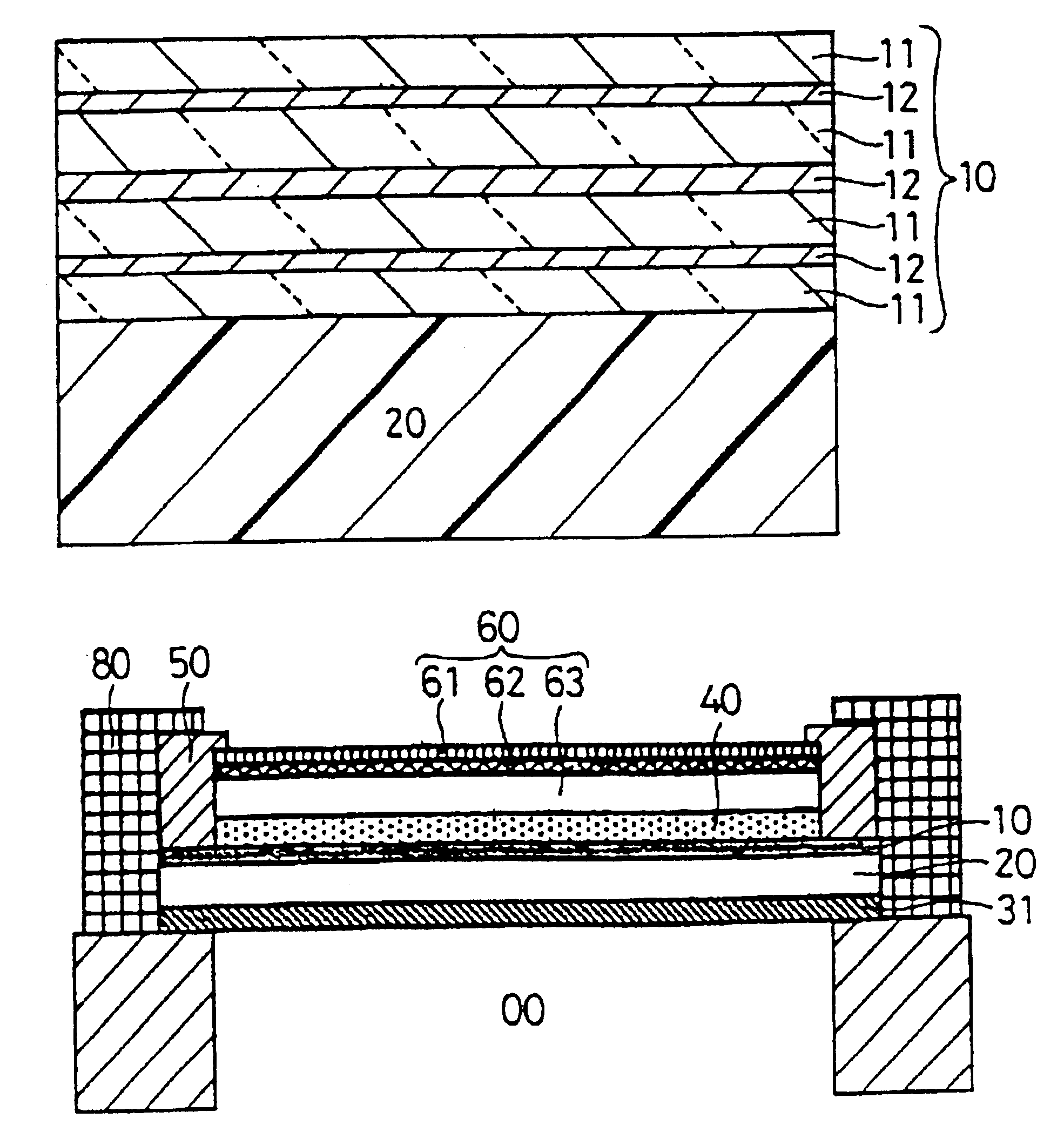
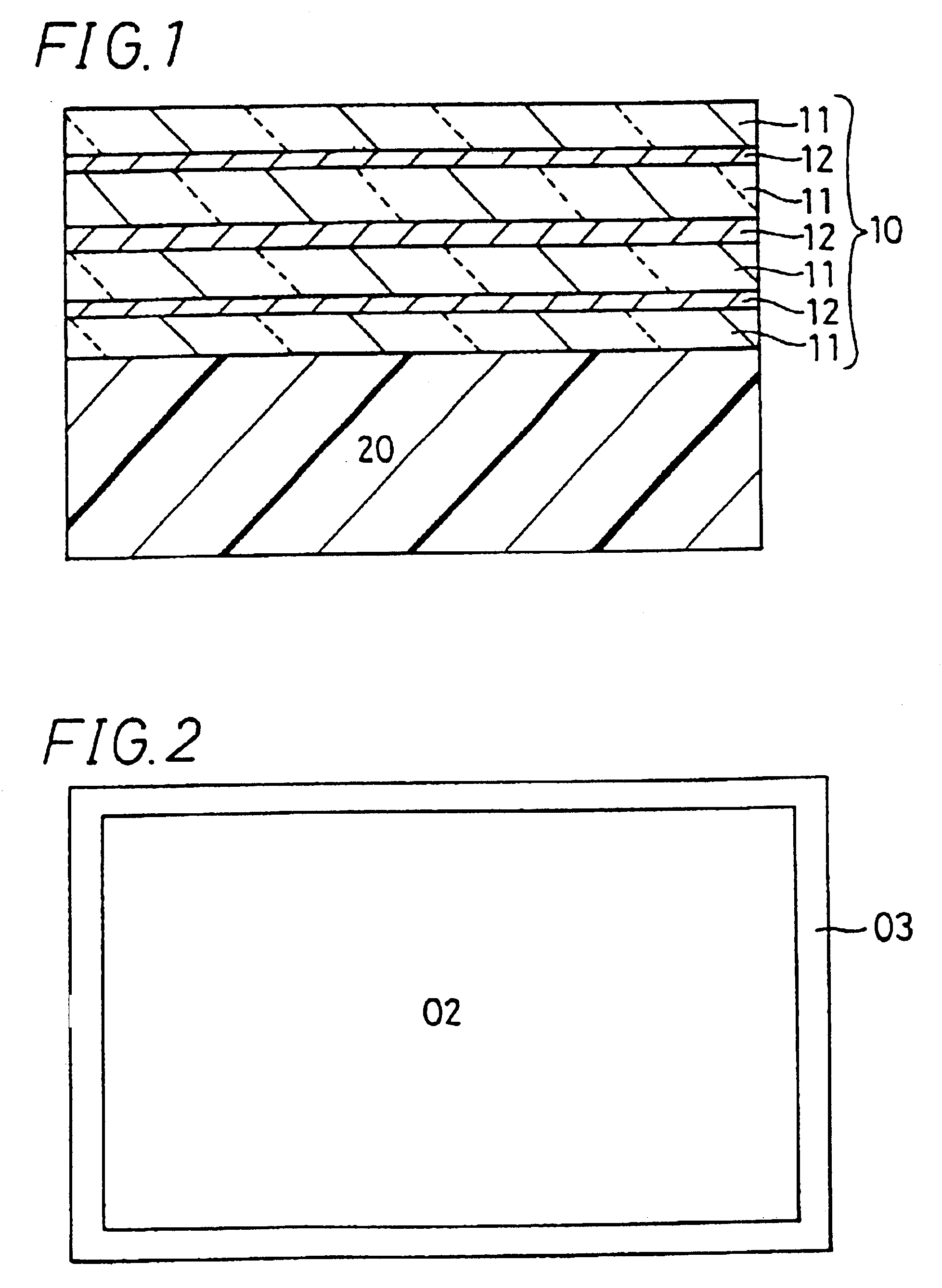
[0332]Designating a biaxially stretched polyethylene terephthalate (hereinafter referred to also as PET) film (188 μm thick) as a polymer film (A), a transparent electrically conductive layer (B) comprising 7 layers in total made up of an ITO thin film (40 nm thick), a silver thin film (11 nm thick), an ITO thin film (95 nm thick), a silver thin film (14 nm thick), an ITO thin film (90 nm thick), a silver thin film (12 nm thick) and an ITO thin film (40 nm thick) in this order as viewed from a side of the PET film was formed on one major surface of the PET film to prepare a transparent laminate 1 comprising the transparent electrically conductive layer (B) having a surface resistance of 2.2 Ω / square.

[0333]A cross-section of a PET film / a transparent electrically conductive layer is shown in FIG. 1 as an example of a polymer film (B) / a transparent electrically conductive layer (D) according to the invention. A reference numeral 10 in FIG. 1 denotes a transparent electrically conductiv...

example 2

[0340]Polyethylene terephthalate pellets 1203 (manufactured by Unitika, Ltd.) were mixed with 0.01% by weight of a red color dye PS-Red-G manufactured by Mitsui Chemicals, Inc. for correcting chromaticity of white color luminescence and 0.015% by weight of a violet color dye PS-Violet-RC manufactured by Mitsui Chemicals, Inc., melted at a temperature of from 260° C. to 280° C. and extruded to form a film having a thickness of 200 μm. Thereafter, this film was biaxially stretched to prepare a PET film (polymer film (B)) containing a dye and having a thickness of 100 μm.

[0341]On one major surface of the PET film, a coating liquid in which alkoxysilane was decomposed by glacial acetic acid and added with a silicone type surface smoothing agent was applied by a gravure coater, and then thermally cured at 120° C. to form a hard coat film (film thickness: 10 μm, pencil hardness: 3H) thereby obtaining a PET film containing a dye in which a hard coat layer (F) is formed. On the hard coat la...

example 3

[0347]In the same manner as in Example 1, a laminate comprising a polymer film (B) / a transparent electrically conductive layer (D) was prepared.

[0348]Further, on a major surface of the PET film / transparent electrically conductive layer wound in roll form, opposite to a PET film thereof, a next functional transparent layer 1 was continuously formed as a functional transparent layer (A) by a roll-to-roll method. Namely, a coating liquid in which a photopolymerization initiator was added to a multi-functional methacrylate resin and, further, ITO fine particles (average particle diameter: 10 nm) were added thereto was applied by a gravure coater and, then, cured by an ultraviolet ray to form an electrically conductive hard coat film (film thickness: 3 μm) and, then, a fluorine-containing organic compound solution was coated on the thus-formed hard coat film by a micro gravure coater and dry-cured at 90° C. to form an anti-reflection film (film thickness: 100 nm) having a refractive inde...


PUM

PropertyMeasurementUnit
wavelength rangeaaaaaaaaaa
transparentaaaaaaaaaa
visible light ray transmittanceaaaaaaaaaa

Abstract

The display filter is constituted by laminating a transparent adhesive layer (C) 31 containing dye, a polymer film (B) 20, a transparent electrically conductive layer (D) 10, a transparent adhesive layer (E) 40, and a functional transparent layer (A) 60 having an anti-reflection property, a hard coat property, a gas barrier property, an antistatic property and an anti-fouling property sequentially in this order, adhered on a display area 00; on this occasion, the transparent electrically conductive layer (D) 10 is grounded to a ground terminal of the display via an electrode 50 and an electrically conductive copper foil adhesive tape 80.

Description

TECHNICAL FIELD[0001]This invention relates to a display filter which is disposed on a screen of a display such as a plasma display (PDP), a Braun tube (CRT), and a liquid crystal display apparatus (LCD) and which has filter characteristics that are capable of shielding other electromagnetic waves than a visible light from among electromagnetic waves to be generated from the display screen and / or other filter characteristics that are capable of correcting a visible light spectrum, a display apparatus mounted with the filter and a method for production of the same.BACKGROUND ART[0002]With the rapid development of information system in society, a photoelectronic component and equipment have been markedly advanced and popularized. Among other things, a display has spread wide for use in a television set, a personal computer, or the like, and the display is required for increasing a size thereof as well as decreasing thickness thereof. A plasma display has attracted attention as a thin-...

Claims


Application Information

Patent Timeline
Patent Type & Authority Patents(United States)
IPC IPC(8): G02B1/11G02B1/10G02B5/22
CPCG02B1/116G02B5/223H05K9/0096H01J2211/446H01J2329/892G02B5/20G02B1/11G02F1/133502
Inventor KOIKE, KATSUHIKOOKAMURA, TOMOYUKIKITAGAWA, TOSHIHISASAIGO, HIROAKIFUKUDA, SHINYAMAZAKI, FUMIHARUNISHIMOTO, TAIZOMISAWA, TSUTAMI
Owner MITSUI CHEM INC
Why Eureka
Try Eureka