Method and apparatus for treating underground pipeline

a technology for underground pipelines and apparatuses, applied in the direction of superimposed coating processes, liquid/solution decomposition chemical coatings, manufacturing tools, etc., can solve the problems of gas leakage at the pipe joints, only temporary preventative procedures, and dilemma in the gas and gas transportation industry, so as to reduce the loss of natural or propane gas and the effect of convenient operation

Inactive Publication Date: 2005-11-22
NEUCO INC
View PDF43 Cites 39 Cited by
  • Summary
  • Abstract
  • Description
  • Claims
  • Application Information

AI Technical Summary

Benefits of technology

[0016]It is a further object of the present invention to provide a rapid coating process, which does not require the coating device to remain in place while the coating material sets.
[0018]It is a further object of the present invention that it can maneuver around bends and other obstacles normally found in gas pipe. It is still a further object of the present invention that it applies a polyurethane sealant that will coat the interior of a variety of different pipe surfaces, with or without the presence of pressurized gas, with or without the presence of air or oxygen and that will not pool in the bottom of the pipe upon application.
[0021]To prevent electric discharge caused by friction, resulting from the individual components of coating material traveling to the coating device, the coating material components can be pumped to the coating device through grounded tubing. This makes the device safer to operate in a live gas environments.
[0022]The device can also include scissor-type expansion legs. These scissor-type legs allow the device to maneuver around corners and bends in the pipe, and to adapt to a wide variety of pipe diameters. Also, the combination of a non-conductive or electrically grounded delivery system with a specially designed pushing system, allow greater lengths of pipe to be sealed or repaired with fewer excavations than known related art devices and techniques.
[0023]Embodiments of the present invention provide an economically feasible method of repair that allows indefinite postponement of the replacement of thousands of miles of gas pipeline, thereby preserving the enormous quantities of natural resources that would be required to fabricate replacement pipe. As many of these pipe joints and other discontinuities are sealed, the loss of natural or propane gas will be greatly reduced, as will the consumption of enormous amounts of glycol and other joint filler preserving compounds.

Problems solved by technology

A dilemma has arisen in the gas and gas transportation industry.
As these filler materials dry out, they decompose and disintegrate, thereby causing gas leaks to appear at the pipe joints.
Unfortunately, these preventative procedures are only temporary, and can be quite costly.
Because many of these pipelines are underground and not readily accessible, excavating, removing and replacing an entire length of pipeline having deteriorated pipe joints is drastic and quite costly.
These leaks are a result of decaying materials such as the material used in the construction of the pipeline, certain types of obstructions or debris which may clog a pipeline, chemical exposure and or crushing due to overburden pressure.
Additionally, without proper treatment, ground water can infiltrate into the broken pipelines.
Further, in water pipelines, obstructions, cracks or other discontinuities can cause areas of reduced water flow, which can result in undesirable bacterial growth.
As described above, because many of these pipelines are also underground and not readily accessible, excavating, removing and replacing an entire length of pipeline having deteriorated pipe joints is drastic and quite costly.
This method can be quite expensive and time consuming.
Also, this method can be dangerous and is unfeasible for small diameter pipe.
Again this is quite costly and may cause an unacceptable reduction in the flow capacity of the pipe.
Also, this method requires a large consumption of natural resources to fabricate a lining for an entire length of pipe, when typically only the joints are susceptible to leaking.
However, this and the above-mentioned methods are not performed on “live gas pipe” (pipe in which pressurized gas remains flowing).
These methods require the gas flow to be shut down for long periods of time.
Depending on the customers being serviced by the gas line, it is normally unacceptable to interrupt service for such long periods of time.
Another disadvantage of these methods is that they require more than a single excavation when coating long lengths of pipeline.
A disadvantage with this device is that it requires an environment free from air and flowing pressurized gas in which to apply sealant.
Another disadvantage with these types of devices is that they are limited in their ability to maneuver around corners or other obstacles in the pipeline as they are in close proximity to the interior of the pipe.
Still another disadvantage with these devices is that they are slow and time consuming because they require the device to remain in place while the sealant sets.
However, as the length of tubing increases, the viscosity of the anaerobic sealant prevents it from reaching the spraying device in adequate quantities.
Also, as the length of tubing increases, static electric charges build up in the line due to the friction caused by the sealant rubbing against the interior of the tubing.
This can pose serious problems when working in a live gas setting.
Another drawback with this device is that the anaerobic sealant tends to pool in the bottom of the pipe upon application.
An additional drawback of this method is that it typically requires the presence of some filler to properly seal a leaking joint.
Because the above-mentioned preventative or fogging measures were never routinely performed in the United States, much of the filler in United States gas pipe joints has disintegrated, making this method of sealing pipe joints impractical.

Method used


Image

  • Method and apparatus for treating underground pipeline
  • Method and apparatus for treating underground pipeline
  • Method and apparatus for treating underground pipeline

Examples


Embodiment Construction

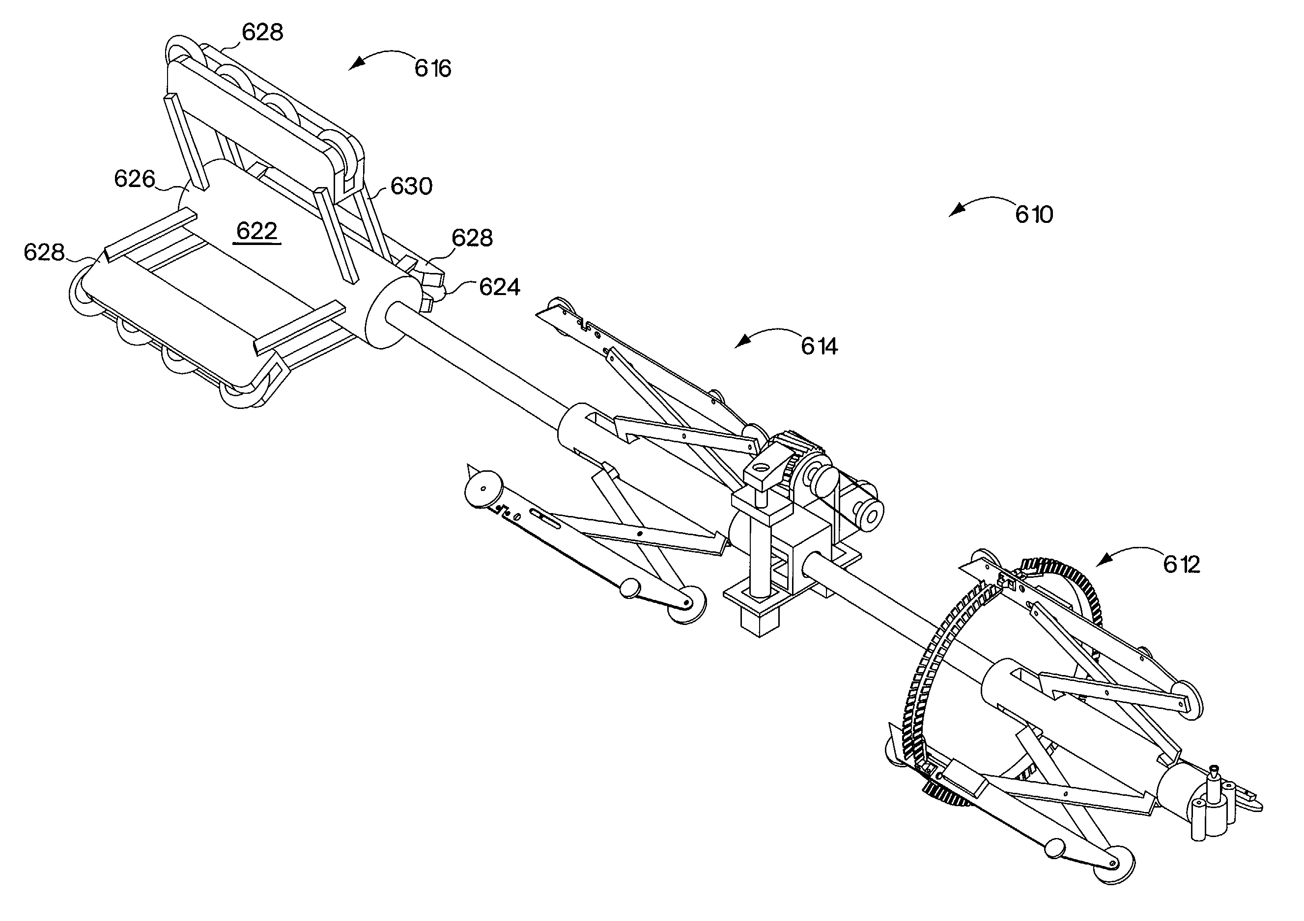
[0063]One embodiment of the present invention will now be described with reference to FIGS. 1–12. Referring now to FIG. 1, a coating device, generally designated by numeral 10, is shown located resting on an inside surface 12 of a pipe 14. The coating device 10 is provided with a centering carriage 20. The centering carriage 20 has a front end 16 and a rear end 18. A manifold 82 is attached to the rear end 18. A containment tube 60 is shown attached to manifold 82. An air motor 38 is mounted inside the front end 16 of centering carriage 20. Air motor 38 turns a rotating slotted head 40. A static mixer 50 is fixed to the side of centering carriage 20. Individual coating material components are sent to the static mixer 50 through intake tubes 86 and 88 where they are thoroughly mixed to produce a coating material 48. The coating material 48 is then sent through an outlet tube 32 where it is forced into a spray tip 36. Spray tip 36 then meters an appropriate amount of coating material ...


PUM

PropertyMeasurementUnit
diameteraaaaaaaaaa
diameteraaaaaaaaaa
temperatureaaaaaaaaaa

Abstract

A system for internally filling a joint or other discontinuity in a pipeline. The system includes a flexible conduit, a fill device removably connected to said flexible conduit, wherein the fill device is constructed and arranged to apply a fill material to an interior surface of said pipeline to fill one or more gaps in the pipeline, and a propulsion unit connected to at least one of the flexible conduit and the fill device that propels the flexible conduit through said pipeline.

Description

RELATED APPLICATIONS[0001]This application is a continuation-in-part of U.S. Ser. No. 09 / 337,578, filed Jun. 22, 1999, now U.S. Pat. No. 6,514,346, which is a continuation-in-part of U.S. Ser. No. 09 / 047,837, filed Mar. 25, 1998, now U.S. Pat. No. 5,913,977, each of which is incorporated herein by reference, and in addition, this application claims priority to Provisional Application 60 / 323,342, filed Sep. 18, 2001, which is also incorporated herein by reference.FIELD OF THE INVENTION[0002]The present invention relates generally to apparatus and methods for internally treating pipeline or conduit. Particularly, this invention relates to treating, bridging, filling and or sealing pipe joints or other discontinuities in situ in a variety of different types of pipeline or conduit, such as live propane, live natural gas, water or sewer pipeline. Even more particularly, this invention relates to internally, milling, filling and sealing pipe joints or other discontinuities in live propane...

Claims


Application Information

Patent Timeline
Patent Type & Authority Patents(United States)
IPC IPC(8): B05B13/06F16L55/1645F16L55/32F16L55/26F16L55/162F16L55/46
CPCB05B13/0636F16L55/1645F16L55/32F16L55/46F16L2101/16Y10S118/10
Inventor WINIEWICZ, ANTHONY E.NICHOLS, RANDALL A.
Owner NEUCO INC
Why Eureka
Try Eureka