Production of catalyst coated membranes

a technology of catalyst coating and membrane, which is applied in the direction of cell components, final product manufacturing, sustainable manufacturing/processing, etc., can solve the problems of difficult to establish the desired ionic contact between the electrode and the membrane, ccms are typically more difficult to manufacture, and it is difficult to apply to commercial manufactur

Inactive Publication Date: 2005-11-22
EI DU PONT DE NEMOURS & CO
View PDF8 Cites 30 Cited by
  • Summary
  • Abstract
  • Description
  • Claims
  • Application Information

AI Technical Summary

Benefits of technology

[0014]The process in accordance with the invention is extremely well-suited to high volume commercial manufacture of catalyst coated membrane. Raised relief printing provides thin, well-distributed layers of the electrocatalyst composition and avoids problems associated with coating techniques which employ large quantities of solvent. The process is extremely versatile and can provide electrodes in any of a wide variety of shapes and patterns and, if desired, can have electrocatalyst or other electrode materials which vary in amount or composition across the electrode, through the thickness of the electrode or both.

Problems solved by technology

In MEA's of this type, it is difficult to establish the desired ionic contact between the electrode and the membrane due to the lack of intimate contact.
Employing CCMs can provide improved performance over forming electrodes on the gas diffusion layer but CCMs are typically more difficult to manufacture.
Techniques that use unhydrolyzed polymer in the membrane, electrocatalyst composition or both can produce excellent CCMs but are difficult to apply to commercial manufacture because a hydrolysis step and subsequent washing steps are required after application of the electrode.
These techniques also can produce good results but mechanical handling and placement of decals on the membrane are difficult to perform in high volume manufacturing operations.
However, the known methods again are difficult to employ in high volume manufacturing operations.
Known coating techniques such as spraying, painting, patch coating and screen printing are typically slow, can cause loss of valuable catalyst and require the application of relatively thick coatings.
Thick coatings contain a large amount of solvent and cause swelling of the membrane which causes it to sag, slump, or droop, resulting in loss of dimensional control of the membrane, handling difficulties during processing, and poor electrode formation.
However, processes employing such pretreatment steps are complicated, difficult to control, and require the removal of large amounts of the vehicle in a drying operation.
Such drying operations are typically slow and require either disposal or recycling of large quantities of the vehicle to comply with applicable environmental requirements.

Method used


Image

  • Production of catalyst coated membranes
  • Production of catalyst coated membranes
  • Production of catalyst coated membranes

Examples


example 1

Preparation of Alcohol Dispersions of Ion Exchange Polymer (Perfluorinated Sulfonic Acid Polymer—Acid Form)

[0050]A 3 liter rotary evaporator flask is charged with 1000 g of a perfluorinated sulfonic acid polymer dispersion (Nafion®—obtained from DuPont), comprising 5 wt % 1100 EW perfluorinated sulfonic acid polymer (PDMOF), in 50% water−50% mixed alcohol (methanol, ethanol, 2-propanol media)). Rotary evaporation is commenced at 60 rpm, 15 mm Hg pressure, with the evaporation flask immersed in a 25° C. H2O bath. A dry ice / acetone bath (−80° C.) is used as the overheads condenser. After several hours of slow, steady operation, 520 gms of H2O / mixed alcohols is removed. As the solids level increased to a nominal 10% level, a noticeable increase in viscosity. (3→20 cps) is observed. A slow approach to this point is necessary to avoid irreversible gelation.

[0051]After a 50 gm sample of the evaporation flask residue is removed, 450 g of n-butanol is added to the evaporation flask. The cle...

example 2

Preparation of Electrocatalyst Coatings Compostions

[0055]Using the above containing perfluorinated sulfonic acid polymer / alcohol dispersions as basic component, catalyst coatings suitable for flexographic printing of CCMs for use in fuel cells are prepared as follows:

[0056]A 13.2 wt % solids perfluorinated sulfonic acid polymer (1100 EW—PDMOF) in n-butanol dispersion, prepared as described above (28.94 g) is combined with 77.31 g n-butanol. The resulting mixture is then cooled down to ˜10° C., well below the 35° C. n-butanol flash point, by the addition of dry ice. This serves to both lower the temperature and to displace the ambient O2 with the generated CO2 gas, thus providing an added margin of safety for the addition of the potentially pyrophoric catalyst powder (platinum supported on carbon). To the cooled mixture, 18.75 g of 60 / 40 C / Pt (E-Tek Corporation) is added slowly with vigorous stirring in order to wet out the powder instantly and to rapidly dissipate the heat of adsorp...

example 3

Preparation of CCM's Utilizing Above Electocatalyst Coating Compositions

[0059]Cyrel® flexographic printing technology (DuPont Company) is used with the above electrocatalyst coating composition to print directly on a variety of perfluorinated sulfonic acid polymer (acid form) film substrates. The press used is a GMS Print Proof system as made by GMS Co. (Manchester, England).

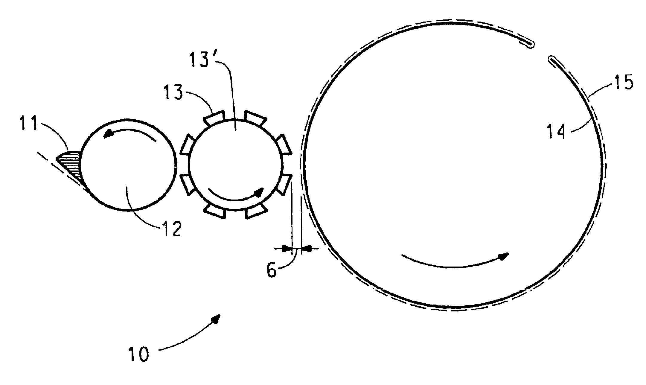
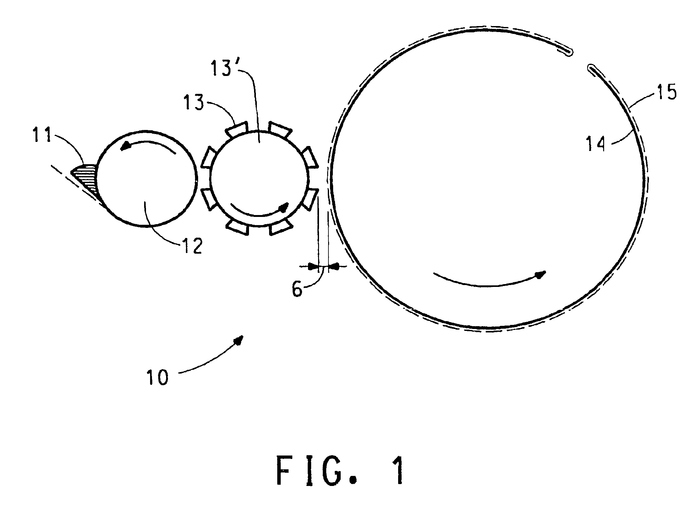
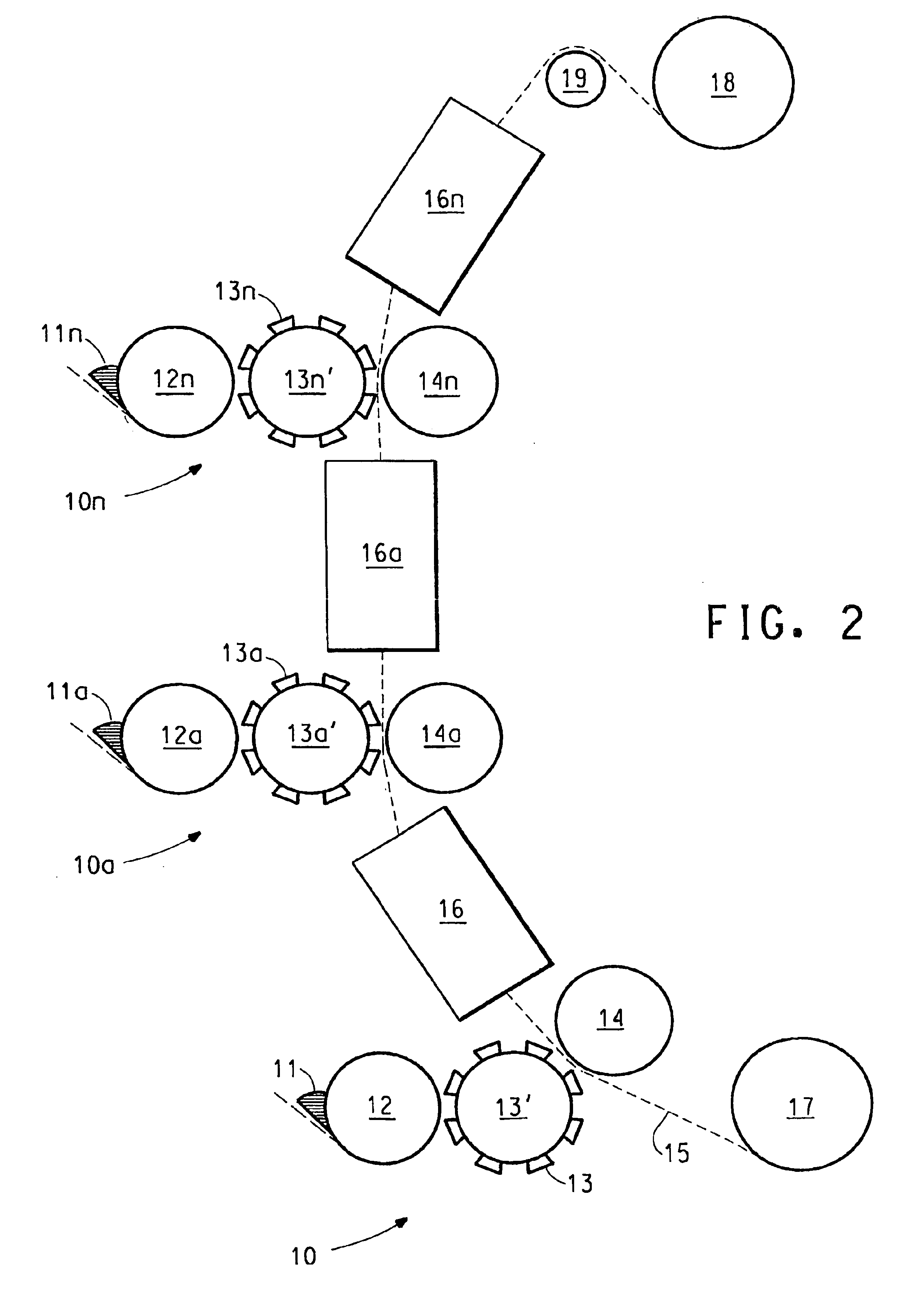
[0060]The as received Cyrel® flexographic plate stock is photo-imaged via strong UV exposure to a precision pattern by a photographic contact negative “tool”. Exposed areas of thick photopolymer mixed film are UV crosslinked. The unexposed areas are next washed away by the appropriate Cyrel® developer solution. Left behind is the cross-linked, rubbery plate surface in sharp relief areas that act to transfer coating compositions in precise patterns and thicknesses to a moving film substrate. The flexographic plate is mounted on a roll which in rotary motion prints the composition on the moving substrate. After pr...


PUM

PropertyMeasurementUnit
sizeaaaaaaaaaa
thicknessaaaaaaaaaa
thicknessaaaaaaaaaa

Abstract

A method for the production of catalyst coated membranes, especially catalyst coated membranes for use in fuel cells, includes raised relief printing a catalyst coating composition (11) onto the surface of an ion exchange membrane (16) to form at least one electrode layer.

Description

[0001]This application is a 371 of PCT / US01 / 51385 filed on Oct. 26, 2001 which claims benefit of application Ser. No. 60 / 243,903 filed Oct. 27, 2000.FIELD OF THE INVENTION[0002]This invention relates to a method for the production of catalyst coated membranes for use in electrochemical cells, especially catalyst coated membranes for use in fuel cells.BACKGROUND OF THE INVENTION[0003]A variety of electrochemical cells falls within a category of cells often referred to as solid polymer electrolyte (“SPE”) cells. An SPE cell typically employs a membrane of a cation exchange polymer that serves as a physical separator between the anode and cathode while also serving as an electrolyte. SPE cells can be operated as electrolytic cells for the production of electrochemical products or they may be operated as fuel cells.[0004]Fuel cells are electrochemical cells that convert reactants, namely fuel and oxidant fluid streams, to generate electric power and reaction products. A broad range of r...

Claims


Application Information

Patent Timeline
Patent Type & Authority Patents(United States)
IPC IPC(8): B05D1/28B05D5/12H01M4/88C25B9/23H01M4/86H01M8/10
CPCC25B9/10H01M4/881H01M4/8828H01M8/1004H01M2300/0082Y02E60/523Y02P70/50Y02E60/50C25B9/23H01M8/02H01M4/88
Inventor O'BRIEN, WILLIAM GEORGE
Owner EI DU PONT DE NEMOURS & CO
Why Eureka
Try Eureka