Process for the manufacture of (poly-)isocyanates in the gas phase

Active Publication Date: 2005-12-13
COVESTRO DEUTSCHLAND AG
8 Cites 31 Cited by

AI-Extracted Technical Summary

Problems solved by technology

The disadvantages of many constructions are high pressure-loss or an arrangement that results in insufficiently rapid mixing or leads to re-mixing in the mixing zone or in the reaction chamber.
High pressure loss in the mixing apparatus results in an increase in the amount of gaseous educt fed in.
However, particularly with educts containing reactive functional groups, the increased boiling temperature causes thermal damage and therefore increases formation of by-products (yield/selectivity losses).
In addition, insufficiently rapid mixing, or re-mixing, leads to ...

Method used

[0032]The arrangement of the multi-nozzle varies preferably from n=2 to 9 individual nozzles of the same construction arranged in the form of a ring. Nozzles arranged in a ring having n=3 to 6 individual nozzles are preferred, n=6 is preferred in particular. Alternatively for example, arrangements of n-1 nozzles arranged in a ring around a centrally-arranged nozzle where n=4 to 8 are also possible. Multi-nozzles having 3 to 7 individual nozzles arranged in a ring and a central nozzle, preferably 5 or 6 individual nozzles arranged in a ring and a c...

Benefits of technology

[0013]The present invention therefore provides a process for the phosgenation of (poly-) amines, with which high yields and high reactor lifetimes can be achieved.
[0014]Advantages of the process according to the invention include: shorter mixing times in comparison with a single nozzle (individual nozzles) of the same area of cross-section and a...

Abstract

The present invention relates to a process for the manufacture of diisocyanates by phosgenation of the corresponding diamines in which the vaporous diamines, optionally rarefied with an inert gas or with the vapors of an inert solvent, and phosgene are heated separately to temperatures of about 200° C. to about 600° C. and mixed and reacted in a tube reactor characterized in that a number n≧2 of nozzles directed parallel to the axis of the tube reactor are arranged in the tube reactor, the diamine-containing stream being fed into the tube reactor through the n nozzles and the phosgene stream being fed into the tube reactor through the remaining free space.

Application Domain

Isocyanic acid derivatives preparationLiquid-gas reaction as foam/aerosol/bubbles +3

Technology Topic

Image

  • Process for the manufacture of (poly-)isocyanates in the gas phase
  • Process for the manufacture of (poly-)isocyanates in the gas phase
  • Process for the manufacture of (poly-)isocyanates in the gas phase

Examples

  • Experimental program(1)

Example

Example 2
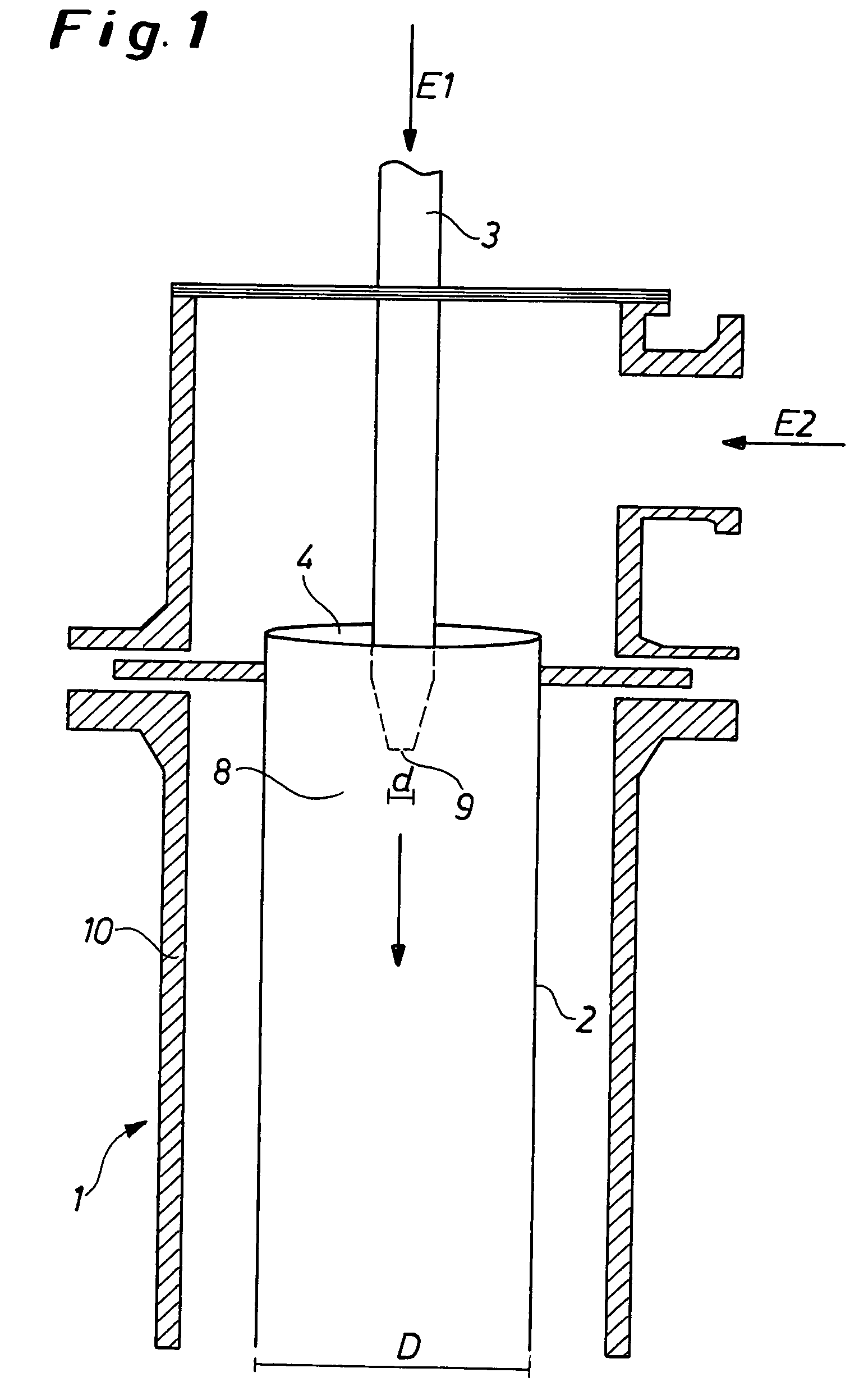
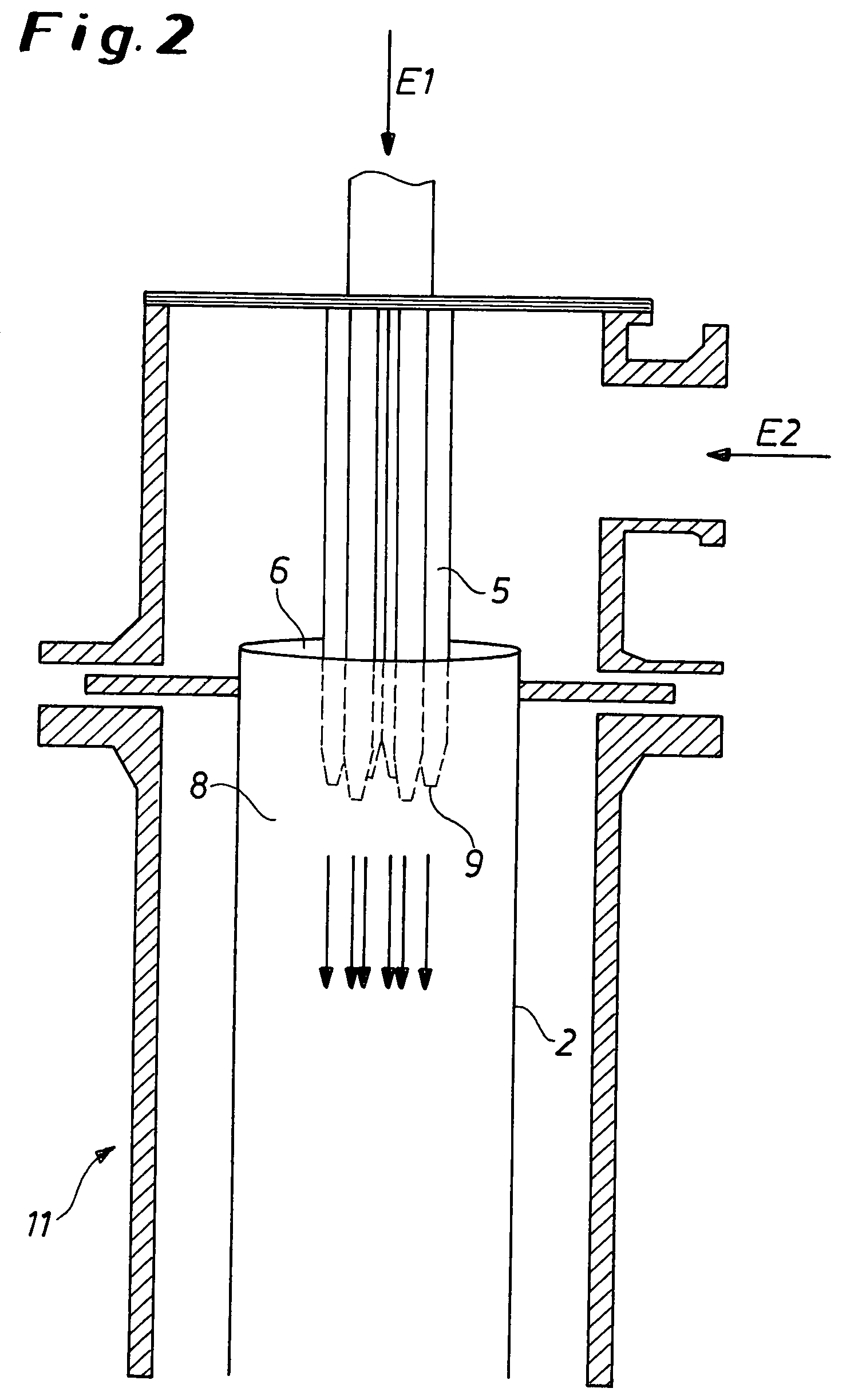
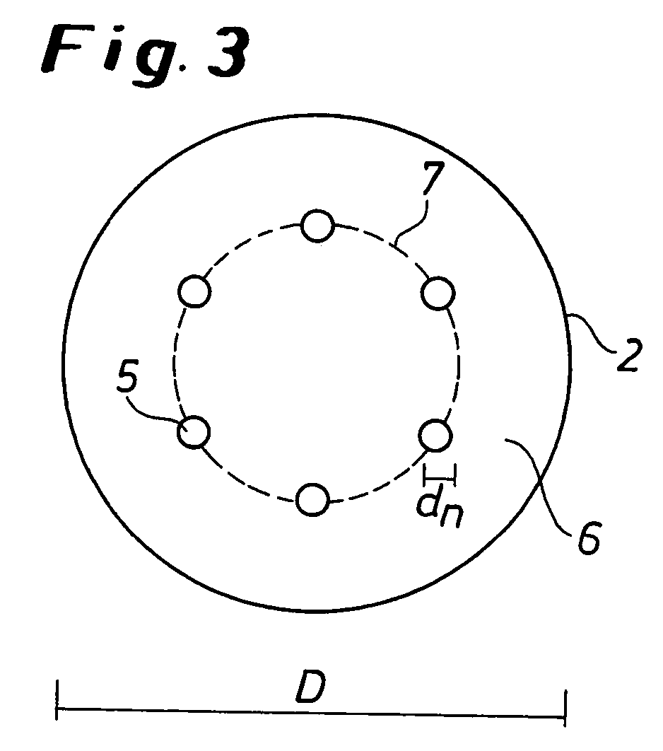
[0039]In a combined mixing and reaction tube 2 according to FIG. 2, followed by an isocyanate condensation step which, in turn, was followed by work-up of the isocyanate, an isomer mixture of 2,4-/2,6 toluene diamine (TDA 80/20), phosgene and nitrogen in a molar ratio of 1:6:0.2 flowed continuously through a multi-nozzle having 6 individual nozzles 5, arranged in a circle, which protrudes into the reaction tube 2. The educts were evaporated separately from each other, in pure form, and superheated to a temperature of 340–370° C. in a preliminary heat exchanger step. A mixture of nitrogen and TDA (E1) flowed though the 6 individual nozzles 5, arranged in a circle, phosgene (E2) flowed in the remaining free space 6 around the individual nozzles 5. The ratio of the area of cross-section of reaction chamber 8 to the total area of the 6 individual nozzles 5 was (as with example 1) 192:1. The pressure in the reaction zone was 1.5 bar. The flow rate of the reaction mixture after the multi-nozzle was about 1.6 m/s. After a residence time of about 2.5 sec in the gas phase, the reaction product 2,4-/2,6-toluylene diisocyanate (TDI 80/20) was condensed by injection cooling at the end of the reaction tube 2, and was then used for de-phosgenation and work up by distillation of the phosgene-containing crude TDI (condensate) and purification of the by-product hydrogen chloride (vapor). The yield of TDI was measured on samples of the phosgene-containing crude TDI at various times during the trial, followed by separation by distillation and quantitative measurement of polymeric by-products and also gas-chromatographic measurement of the TDI content of the distillate in the laboratory. The TDI yield was max. 98.4% of theoretical in relation to the TDA used. The selected arrangement allowed for very even operation. After controlled termination of the reaction and checking of the reactor for contamination after 114 h operation, only slight, evenly-distributed areas of contamination were detected in the upper reaction area, which would not present any disadvantages for flow during longer periods of continuous operation.
[0040]Although the invention has been described in detail in the foregoing for the purpose of illustration, it is to be understood that such detail is solely for that purpose and that variations can be made therein by those skilled in the art without departing from the spirit and scope of the invention except as it may be limited by the claims.

PUM

PropertyMeasurementUnit
Temperature200.0°C
Temperature600.0°C
Temperature250.0°C
tensileMPa
Particle sizePa
strength10

Description & Claims & Application Information

We can also present the details of the Description, Claims and Application information to help users get a comprehensive understanding of the technical details of the patent, such as background art, summary of invention, brief description of drawings, description of embodiments, and other original content. On the other hand, users can also determine the specific scope of protection of the technology through the list of claims; as well as understand the changes in the life cycle of the technology with the presentation of the patent timeline. Login to view more.

Similar technology patents

Method and device for processing slaughter products

InactiveUS6912434B2High yieldHigh profitElectric current slaughtering/stunningGas slaughtering/stunningComputer science
Owner:STORK PMT

Classification and recommendation of technical efficacy words

  • Short mixing time
  • High yield

Sand mixing and stirring cage of precoated sand mixing machine

InactiveCN104646618AShort mixing timeReduce lossesMould handling/dressing devicesEngineeringMixing tank
Owner:WUXI KANGHUI MACHINE BUILDING
Why Eureka
Try Eureka