High intensity discharge lamp ballast apparatus

a high-intensity discharge and lamp ballast technology, which is applied in the direction of electric variable regulation, process and machine control, instruments, etc., can solve the problems of preventing implementation, increasing the size of transformers, the number of components, and hampering the reduction in size and cost of high-intensity discharge lamp ballast apparatuses, etc., to reduce the size of the apparatus, reduce the size of the circuit, and the effect of sufficient energy

Inactive Publication Date: 2005-12-13
MITSUBISHI ELECTRIC CORP
View PDF11 Cites 31 Cited by
  • Summary
  • Abstract
  • Description
  • Claims
  • Application Information

AI Technical Summary

Benefits of technology

[0015]The present invention is implemented to solve the foregoing problems. It is therefore an object of the present invention to provide a compact, inexpensive high intensity discharge lamp ballast apparatus capable of turning on the metal halide lamp normally without flickering out at the discharge start by using the one-stage high frequency boosting inverter system.
[0017]The high intensity discharge lamp ballast apparatus includes the DC-AC inverter for converting the DC voltage to the AC voltage with boosting it, and the first resonance circuit and second resonance circuit on the secondary side of the transformer of the DC-AC inverter. This makes it possible to downsize the circuit, and supply sufficient energy to the high intensity discharge lamp during the discharge developing period. As a result, it offers an advantage of being able to reduce the size of the apparatus that carries out the normal ballasting of the metal halide lamp.

Problems solved by technology

To apply the circuit scheme to the ballast apparatus of the metal halide lamp, the unique requirements of the metal halide lamp must be met, which prevents the implementation thereof.
This increases the size of the transformer, and the number of the components, thereby presenting a problem of hampering the reduction in size and cost of the high intensity discharge lamp ballast apparatus.
This presents a problem of hindering the reduction in cost and size of the high intensity discharge lamp ballast apparatus.
This increases the size and cost of the transformer and capacitor, and the number of components, thereby presenting a problem of preventing the reduction in size and cost of the high intensity discharge lamp ballast apparatus.

Method used


Image

  • High intensity discharge lamp ballast apparatus
  • High intensity discharge lamp ballast apparatus
  • High intensity discharge lamp ballast apparatus

Examples


embodiment 1

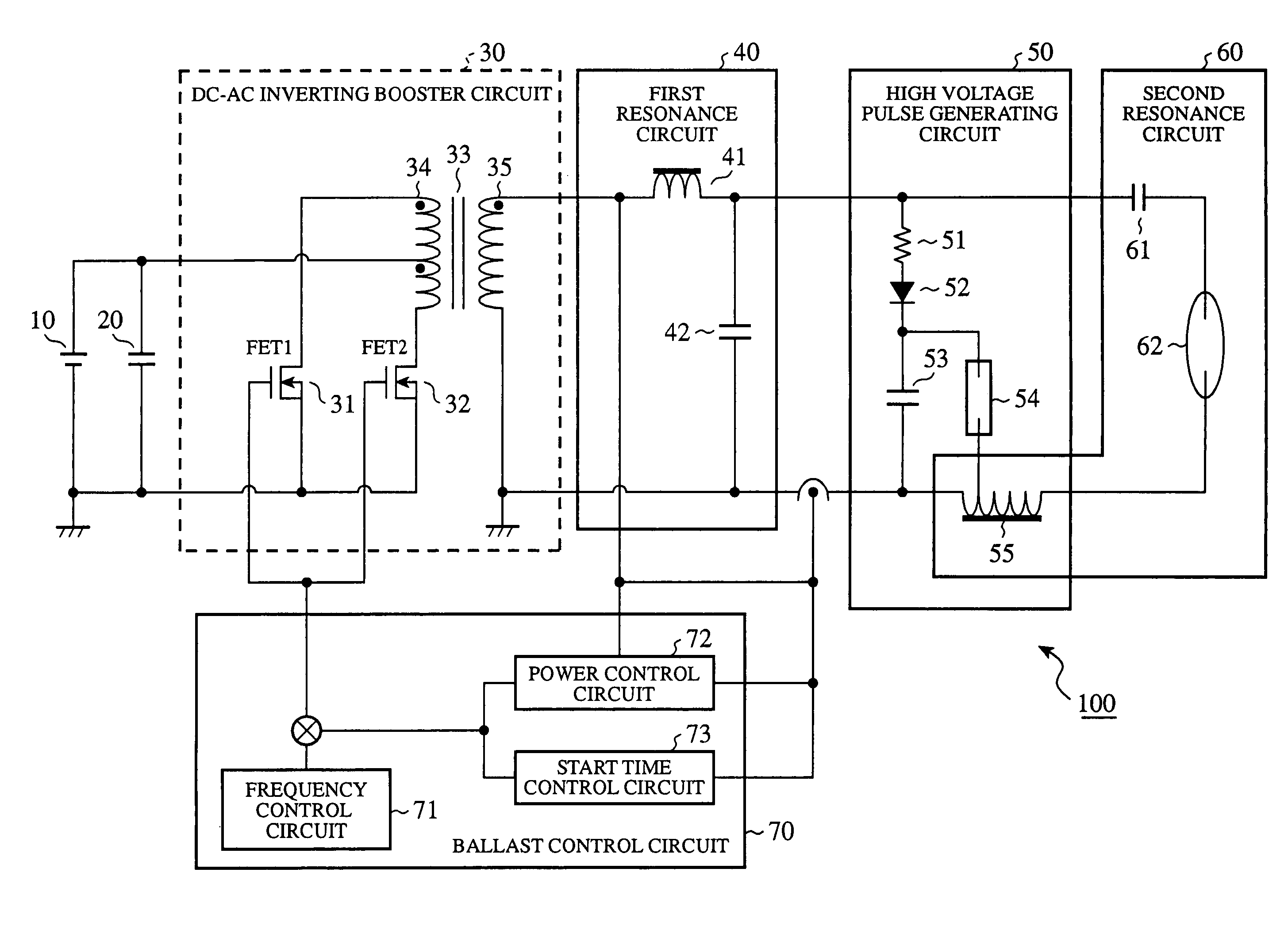
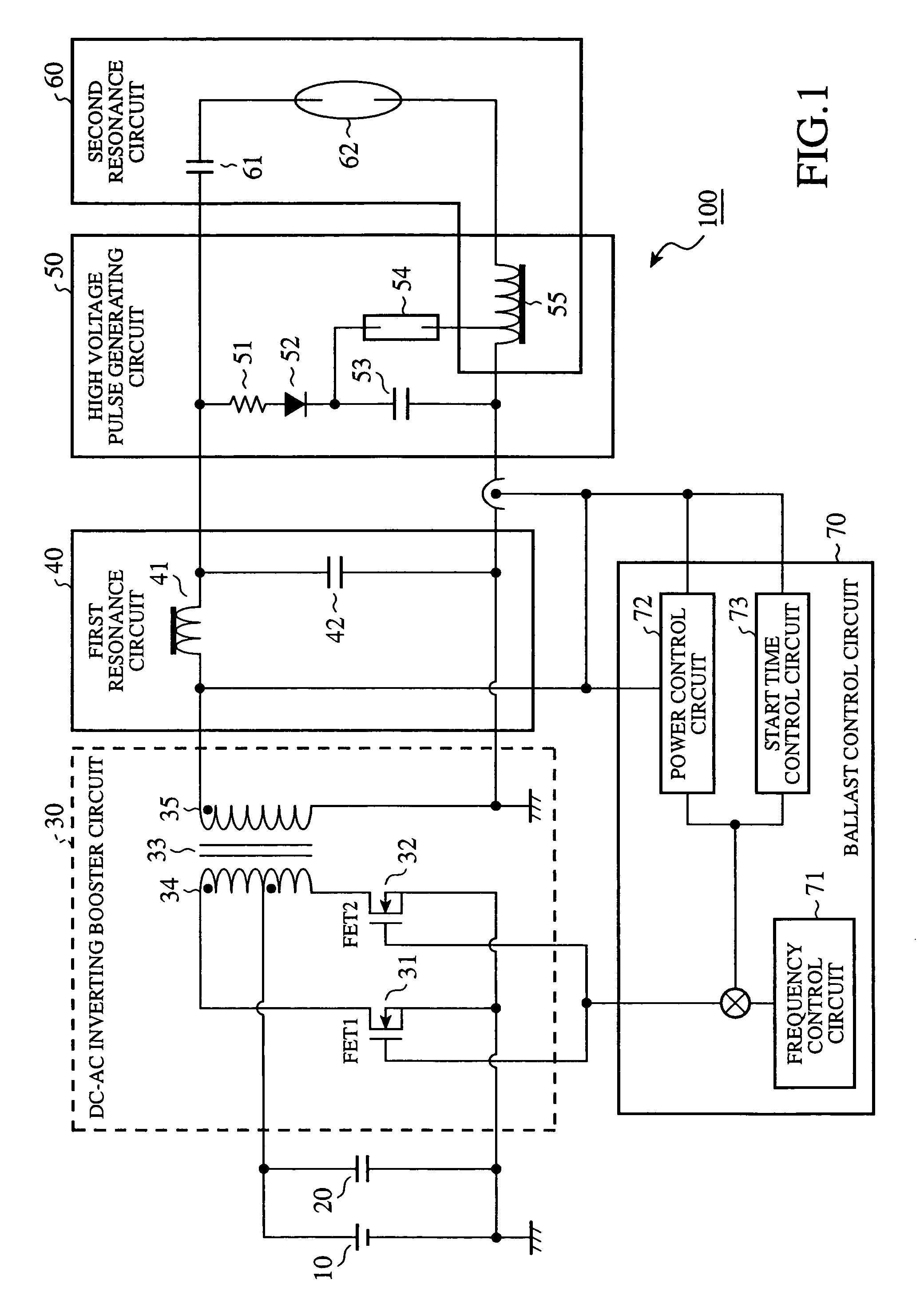
[0026]FIG. 1 is a circuit diagram showing a configuration of a metal halide lamp ballast apparatus 100 (high intensity discharge lamp ballast apparatus) of an embodiment 1 in accordance with the present invention. As shown in FIG. 1, the metal halide lamp ballast apparatus 100 includes a DC power supply 10 such as a battery, a smoothing capacitor 20, a DC-AC inverting booster circuit 30 (DC-AC inverter), a first resonance circuit 40, a high voltage pulse generating circuit 50, a second resonance circuit 60, and a ballast control circuit 70.

[0027]The DC-AC inverting booster circuit 30 has a FET (Field Effect Transistor) 31 and a FET 32 (switching element), and a DC-AC converter transformer 33 (transformer). The FETs 31 and 32 are each turned on and off in response to a pulse signal fed from the ballast control circuit 70 to their gates. Thus, the current flowing through the primary winding 34 of the DC-AC converter transformer 33 is altered so that a rectangular wave voltage is gener...


PUM


Abstract

A compact, low cost high intensity discharge lamp ballast apparatus which can carry out normal ballasting without extinction at discharge start includes a DC-AC inverting booster circuit, a first resonance circuit, and a second resonance circuit. The DC-AC inverting booster circuit includes a DC-AC converter transformer for converting a DC voltage fed from a DC power supply to an AC voltage in response to switching on and off of FETs, boosting the voltage. The first resonance circuit includes a leakage inductance connected in series with the secondary winding of the DC-AC converter transformer, and a first resonant capacitor connected in parallel with the secondary winding. The second resonance circuit includes a metal halide lamp, an ignitor transformer for producing a voltage to start lighting of the metal halide lamp, and a second resonant capacitor.

Description

BACKGROUND OF THE INVENTION[0001]1. Field of the Invention[0002]The present invention relates to a high intensity discharge lamp ballast apparatus.[0003]2. Description of Related Art[0004]Recently, metal halide lamps have been used as the headlights of an automobile instead of halogen lamps. The metal halide lamp, one of the HID (High Intensity Discharge) lamps, is characterized by its high luminous efficiency, high color temperature and long life compared with the halogen lamp. The arc tube of the metal halide lamp contains metal halides which are mixtures of some metals such as sodium and scandium with halogen such as iodine, high pressure xenon serving as a starting gas, and mercury. The metal halide lamp starts emitting light as follows. First, it starts discharge of the xenon in a gaseous condition at room temperature, followed by arc discharge of the xenon, which increases the temperature inside the arc tube. As the temperature in the tube increases, the mercury vaporizes and ...

Claims


Application Information

Patent Timeline
Patent Type & Authority Patents(United States)
IPC IPC(8): H05B41/288H05B41/38H05B41/24
CPCH05B41/2881H05B41/2886H05B41/388Y02B20/202Y02B20/204Y10S315/07Y02B20/00
Inventor IZUMI, KIKUOHARADA, SHIGEKIIWATA, AKIHIKOOHSAWA, TAKASHI
Owner MITSUBISHI ELECTRIC CORP
Why Eureka
Try Eureka