
Apparatus for the controlled optimized addition of reactants in continuous flow reaction systems

a technology of reactant and reaction system, applied in the direction of stationary tubular conduit assembly, steam/vapor condenser, water/sludge/sewage treatment, etc., can solve the problem of limiting the ratio of oxidant to hydrocarbon feed, and reducing the efficiency of catalyst performan

Inactive Publication Date: 2005-12-20
SAUDI BASIC IND CORP SA
View PDF30 Cites 42 Cited by
  • Summary
  • Abstract
  • Description
  • Claims
  • Application Information

AI Technical Summary

Benefits of technology

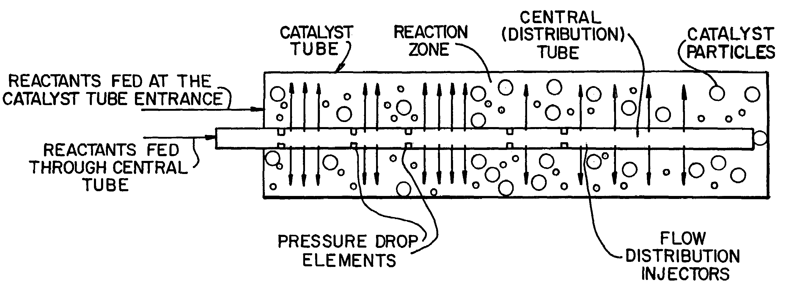
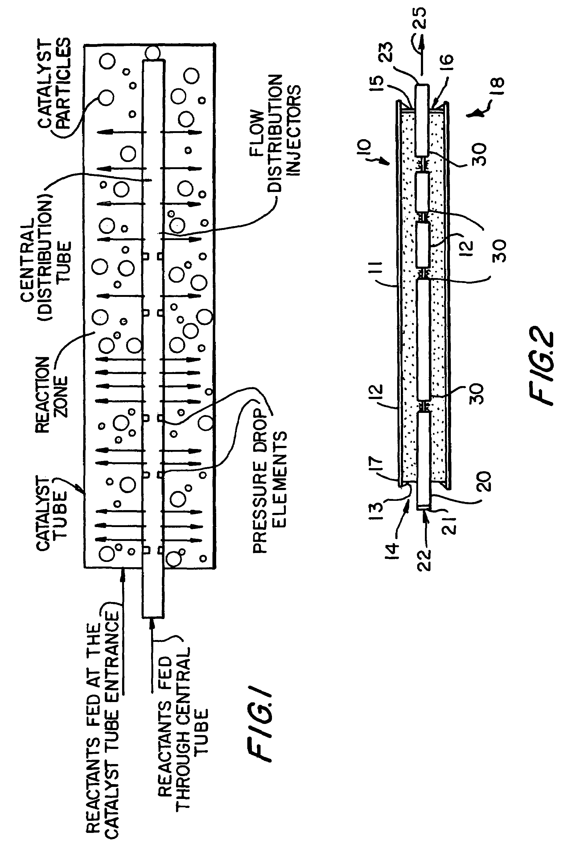
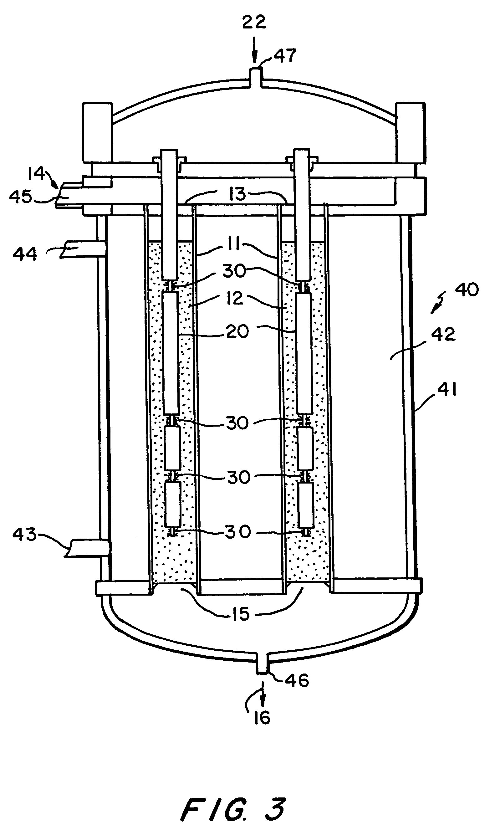
[0018]It is another object of the invention to provide an improved continuous flow chemical reaction system where a controlled amount of at least one fluid reactant is introduced into the reaction zone at more than one location.
[0033]Furthermore, the invention improves catalyst performance by the delayed addition of a component which reverts its reduction / oxidation state or a component which remedies a catalyst poisoning situation.

Problems solved by technology

The oxidative dehydrogenation reaction, however, raises problems such as: (a) removal of the exothermic heat of reaction, (b) possible associated temperature runaway, (c) control of selectivity to desired product, and (d) limiting the formation of undesired oxygenated by-products and carbon oxides.
Another problem which is associated with oxydehydrogenation processes, as well as oxidation processes, is the limitation on the oxidant to hydrocarbon feed ratios which is imposed by the explosive mixture formation constraint.
This problem compromises the ability of the process to achieve optimality of feed compositions that satisfy the stoichiometric and kinetic requirements of the reaction, yet avoid compositions which can lead to autoignition, deflagration, and detonation.

Method used


Image

  • Apparatus for the controlled optimized addition of reactants in continuous flow reaction systems
  • Apparatus for the controlled optimized addition of reactants in continuous flow reaction systems
  • Apparatus for the controlled optimized addition of reactants in continuous flow reaction systems

Examples


example 1

[0093]Partial oxidation of ethane to ethylene and acetic acid is utilized here as a model reaction to demonstrate the benefit of the present invention. Kinetics developed by Thorstienson et al., Journal of Catalysis, vol. 52, pp. 116–132 (1978) are used to describe the rates of reactions involved on this partial oxidation process, those reactions are:[0094]C2H6+0.5O2→C2H4+H2O[0095]C2H4+O2→CH3COOH[0096]C2H6+3.5O2→2CO2+3H2O[0097]C2H4+2O2→2CO+2H2O[0098]CH3COOH+O2→2O+2H2O[0099]CO+0.5O2→CO2 [0100]C2H4+3.0O2→2CO2+2H2O

[0101]Model equations have been developed for the catalyst tube resulting in a system of non-linear ordinary differential equations which were solved numerically to predict the non-isothermal behavior of the reaction. This is to calculate the reacting mixture compositions, pressure and temperature at each point along the length of the reactor tube.

[0102]The model was then used to simulate operating scenarios where the target in each one was to maximize the production of ethyl...

example 2

[0110]The reaction of ethane oxidation was performed using a pilot scale testing unit illustrated in FIG. 13. The following is a description of the testing rig:

[0111]A. Feed Section

[0112]The feed section consisted mainly of clusters of compressed gas cylinders with manifolds and mass flow controllers. The feed section was constructed to feed into the reactor the following reactants: ethane, air, oxygen, carbon dioxide and nitrogen. Mass flow controllers on each gas feed line were operated from a remote location. A forward pressure regulator on each gas feed line maintained the desired pressure of the reactants.

[0113]B. Reactor Section

[0114]The prototype multi-injection reactor was constructed from 316 stainless steel with a length of 12.5 m. It was bent into a U-shape to keep the structure within a reasonable height. The reactor consisted of an inner (distribution) tube, a thermowell, an outer tube and a shell. The inner tube and the thermowell were situated inside the outer tube, w...


PUM

PropertyMeasurementUnit
pressureaaaaaaaaaa
temperatureaaaaaaaaaa

Abstract

An apparatus for performing continuous flow chemical reactions such as oxidation, oxidative dehydrogenation and partial oxidation processes involving a reactor design characterized by controlled / optimized addition of a reactant with the objective of: (i) avoiding the explosion regime of the reactant mixture (e.g., hydrocarbon / oxidant mixture); (ii) maximizing the selectivity of the reaction to the desired product; (iii) limiting the reactor temperature gradient and therefore the threat of reaction runaway; and (iv) controlling the operating temperature of the reaction zone so that desirable temperature range is maintained over the entire zone.

Description

BACKGROUND OF THE INVENTION[0001]1. Field of the Invention[0002]The present invention relates to an improved continuous flow chemical reaction apparatus wherein the introduction of at least one reactant feed into the reaction zone is optimized. The invention also relates to improved chemical reactions achieved using the continuous flow chemical reaction apparatus.[0003]2. Description of Related Art[0004]Several publications are referenced in this application. The references describe the state of the art to which this invention pertains, and are hereby incorporated by reference.[0005]An oxidative dehydrogenation, or partial oxidation, process is a one step conversion of light hydrocarbons to olefins and carboxylic acids. The process potentially offers many advantages over cracking and pure dehydrogenation which are extremely capital intensive and energy intensive. The conversion of saturated hydrocarbons into olefins and carboxylic acids over low temperature catalysts was disclosed b...

Claims


Application Information

Patent Timeline
Patent Type & Authority Patents(United States)
IPC IPC(8): B01J4/00B01J8/06B01J8/18B01J8/24B01J19/00B01J19/24B01J19/26
CPCB01J8/065B01J8/067B01J8/1827B01J8/1836B01J8/26B01J19/0013B01J19/002B01J19/2415B01J19/2425B01J19/244B01J19/26B01J2208/00106B01J2208/00212B01J2208/0023B01J2208/00256B01J2208/0053B01J2208/00539B01J2208/00548B01J2219/00033B01J2219/00074B01J2219/00162B01J2219/00259B01J2219/00263B01J19/00
Inventor ADRIS, ALAA ELDIN M.AL-SHEREHY, FAHAD A.SOLIMAN, MUSTAFA A.HAKEEM, TARIQUEKAREEMUDDIN, SHICKHAL-NUTAIFI, ABDULLAH A.SAUDAGAR, MUNAWWARAZAM, SHAHID M.
Owner SAUDI BASIC IND CORP SA
Learn More